erature: 350 ± 5
o
C
• Soldering time: Within 4 seconds
• Soldering combination: Sn-3.0Ag-0.5Cu
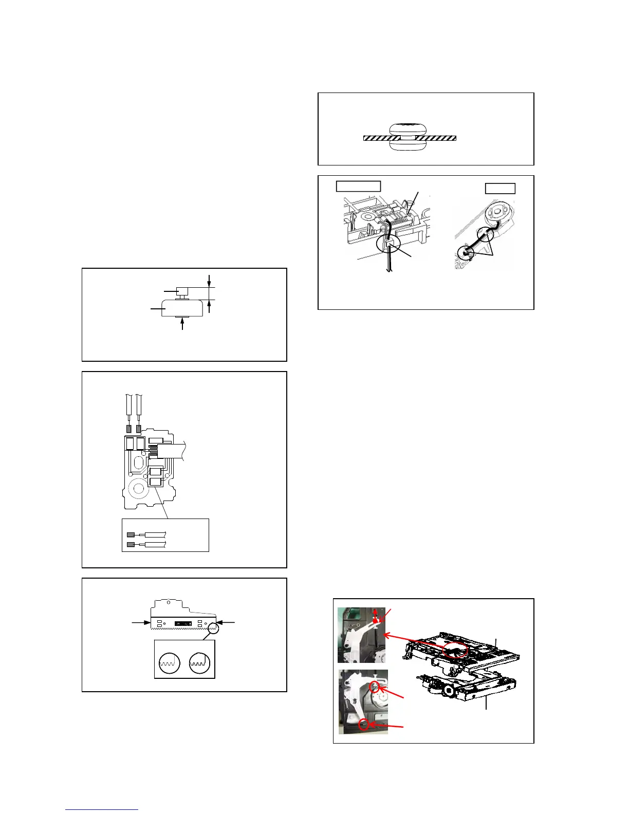
3. When installing the Feed Rack Ass'y, push both ends to
align the teeth as shown Fig. 2-2-D. Then install it.
4. In case of the Insulator (R) installation, install correctly as
Fig. 2-2-E.
5. After the assembly of the Traverse Ass'y, hook the wire
on the Traverse Ass'y as shown Fig. 2-2-F.
• In case of remove FEED MOTOR that has to arrange wire as following
7.0 ± 0.1mm
the picture on above.
2.3: GEAR ROLLER/LUMIRROR WASHER/
ROLLER CONE/SHAFT ROLLER/
LOADING MOTOR PCB/LOADING MOTOR/
GEAR WORM/RACK LEVER (Refer to Fig. 2-3-B)
DISASSEMBLY INSTRUCTIONS
Insulator (R)
Gear Motor
Feed Motor
Safety surface for pressing of the insert.
Fig. 2-2-B
Fig. 2-2-E
Traverse Ass'y (Top Side)
Fig. 2-2-F
Check Hook
Traverse Ass'y
Check Hook
UP SIDE
BOTTOM
B2-2
1. Remove the 3 screws (1).
~FEED MOTOR~
2. Remove the Chassis Main Ass'y.
3. Remove the Roller Ass'y.
4. Remove the Gear Roller.
5. Remove the Lumirror Washer.
• Install wire from (1) to (4) in order.
6. Remove the Roller Cone.
7. Remove the Shaft Roller .
8. Remove the screw (2).
9. Remove the Loading Motor PCB Ass'y.
10. Remove the screw (3).
11. Remove the Loading Motor.
12. Remove the Gear Worm.
13. Remove the Rack Lever.
NOTE
1. When Chassis Main Ass'y is removed, it is necessary to
change the position of Lever Disc and Guide Disc.
2. In case of the Chassis Main Ass'y, check position Lever
Disc, Lever Guide and Boss of Rack Disc Sensor as shown
Feed Rack Ass'y Fig. 2-3-A.
• Remove the Lever Guide in the direction of arrow.
(OK) (NG)
PCB630
Fig. 2-2-C
Push
Push
Fig. 2-2-D
~FEED MOTOR~
WHITE(3)
BROWN(4)
GREEN(1)
YELLOW(2)
Fig. 2-3-A
Check Boss
Check Position
Chassis Main Ass'y
Frame Main Ass'y
Lever Guide
B2-2