• Screw Torque: 1.0 ± 0.3kgf•cm (Screw (3))
(OK) (NG)
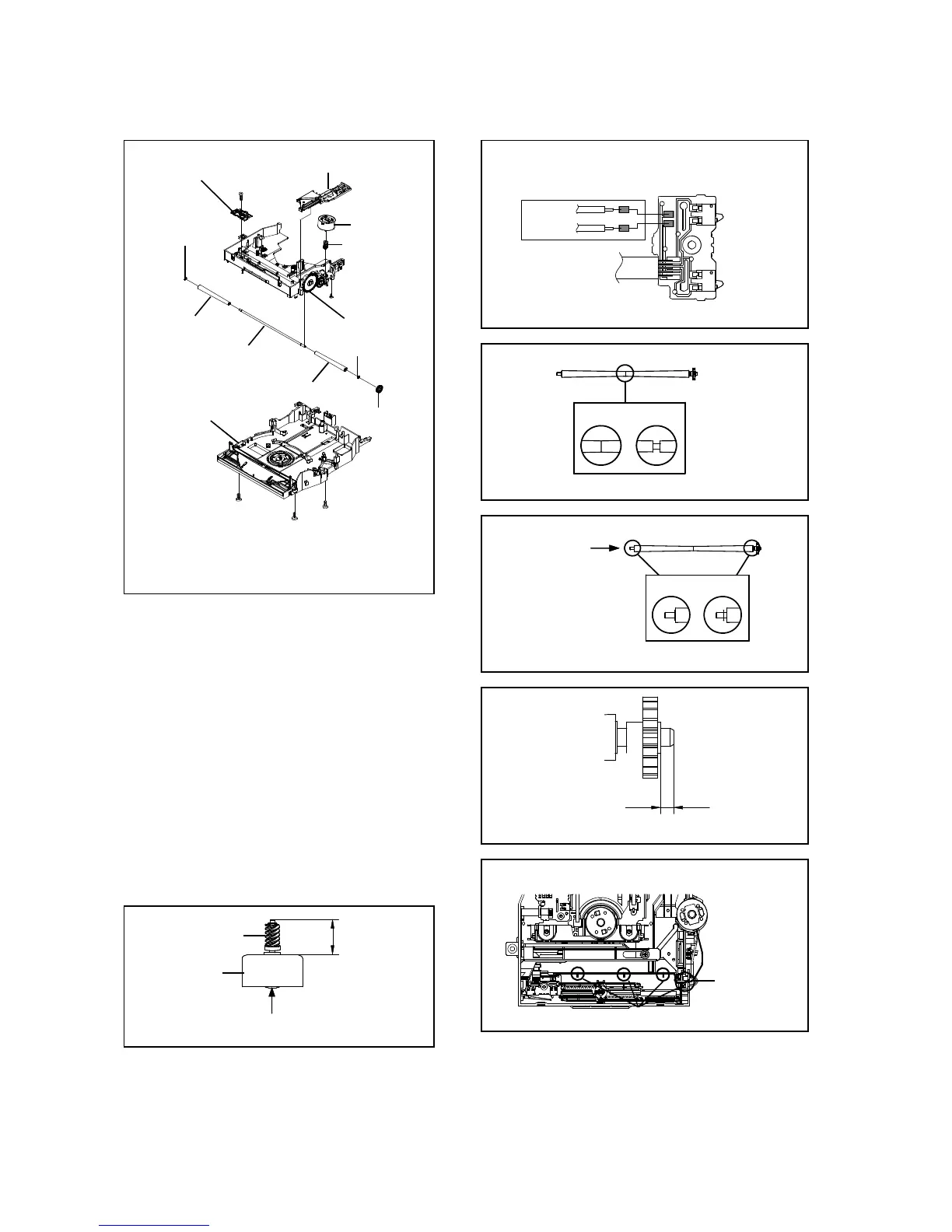
NOTE
1. In case of the Gear Worm installation, check if the value
of the Fig. 2-3-C is correct.
2. When installing the wire of the Loading Motor PCB Ass'y,
install it correctly as Fig. 2-3-D.
Manual soldering conditions
• Solderin
erature: 350 ± 5
o
C
• Soldering time: Within 4 seconds
• Soldering combination: Sn-3.0Ag-0.5Cu
3. In case of the Roller Cone installation, install correctly as
Fig. 2-3-E.
4. In case of the Lumirror Washer installation,
install correctly as Fig. 2-3-F.
1.8 + 0, - 0.1mm
5. In case of the Gear Roller installation, check if the value
of the Fig. 2-3-G is correct.
6. After the assembly of the Loader Sub Ass'y, hook the wire
on the Loader Sub Ass'y as shown Fig. 2-3-H.
14.3 + 0, - 0.1mm
Loader Sub Ass'y
Fig. 2-3-B
Gear Worm
Loading Motor
Safety surface for pressing of the insert.
Fig. 2-3-C
Fig. 2-3-G
Roller Sub Ass'y
Fig. 2-3-F
Fig. 2-3-H
Check Hook
Check Hook
Safety surface for
pressing of the insert.
B2-3