112
LC-26GA5E
LC-32GA5E
LC-26GA5E
LC-32GA5E
Table 2 -5 provides detailed Microprocessor Interface pin descriptions.
DOG0 121 I/O SR5
DOPort Green Pixel Data. In dual pixel output mode these pins are the
ODD green outputs. In single pixel output mode these pins are not used.
DOG1 120 I/O SR5
DOG2 119 I/O SR5
DOG3 118 I/O SR5
DOG4 117 I/O SR5
DOG5 116 I/O SR5
DOG6 115 I/O SR5
DOG7 114 I/O SR5
DOB0 113 I/O SR5
DOPort Blue Pixel Data. In dual pixel output mode these pins are the ODD
blue outputs. In single pixel output mode these pins are not used.
DOB1 112 I/O SR5
DOB2 111 I/O SR5
DOB3 110 I/O SR5
DOB4 109 I/O SR5
DOB5 108 I/O SR5
DOB6 100 I/O SR5
DOB7 99 I/O SR5
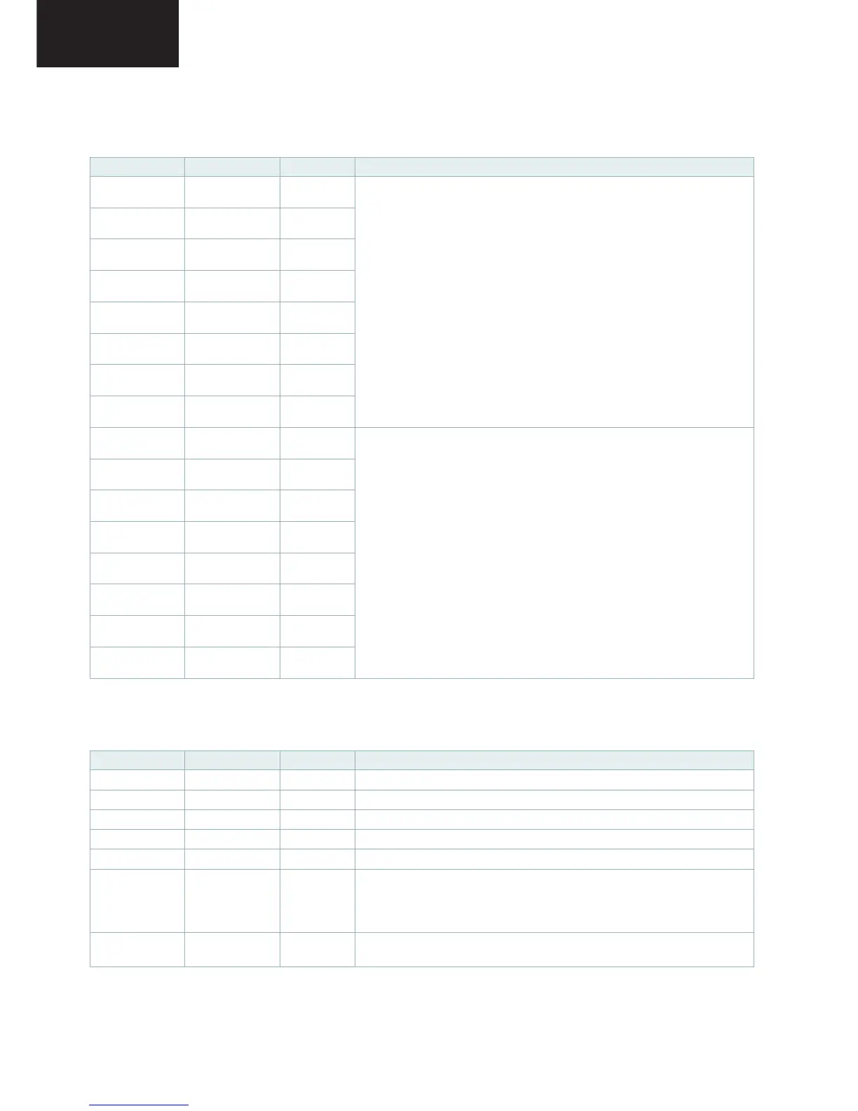
Table 2-5 Microprocessor Interface Pin Descriptions
Name
Pin(s) Type Function
WR 195 I/O D5
Write Enable. Low indicates a write to external RAM or other devices.
RD 196 I/O D5
Read Enable. Low indicates a read to external RAM or other devices.
ROMOE 197 OS
ROM Output Enable. Low output indicates a read from external ROM.
ROMWE 198 OS
ROM Write Enable. Low indicates a write to external ROM.
CS0 199 I/O D5
Miscellaneous Chip Select 0. Low selects external devices.
CS1 200 I/O D5
Miscellaneous Chip Select 1. When EXTRAMEN=0, low selects external
devices.
Chip select for external RAM. When EXTRAMEN=1, low selects external
RAM. (RAMCS)
NMI 194 ID 5
Non-Maskable Interrupt. A high input triggers a non-maskable interrupt to
the on-chip microprocessor.
Table 2-4 Display/Odd Port Pin Descriptions (continued)
Name Pin(s) Type Function
3.3. Description of Pins IC2201, continued
CONFIDENTIAL