8
LC-26GA5E
LC-32GA5E
LC-26GA5E
LC-32GA5E
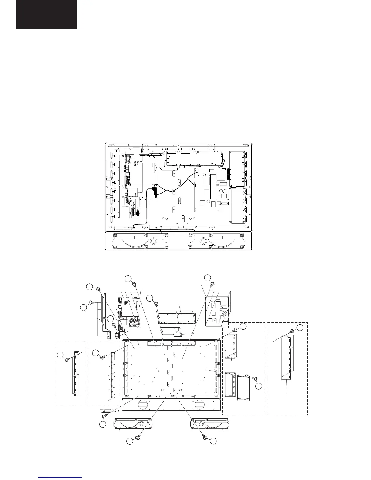
7. Disconnect all the connectors from all the PWBs.
8. Remove the MAIN and COMPONENT PWBs.
8-1. Remove the 3 lock screws 9 and the 2 lock screws 0. Detach the Chassis Frame.
8-2. Remove the 1 lock screw q and detach the COMPONENT PWB.
8-3. Remove the 5 lock screws w and detach the MAIN PWB.
9. Remove the 2 lock screws e and detach the R/C,LED PWB
10. Remove the 3 (LC-26GA5E) / 6 (LC-32GA5E) lock screws r and detach the INVERTER GND PWB.
11. LC-26GA5E : Remove the 4 lock screws t and detach the INVERTER PWB.
LC-32GA5E : Remove the 8 lock screws t and detach the INVERTER-A and INVERTER-B PWBs.
12. Remove the 6 lock screws y and detach the LCD CONTROLLER PWB and Heat Sink.
13. Remove the 6 lock screws u and detach the POWER PWB.
14. Remove the 2 lock screws i and detach theSP BOX (L) and (R). (LC-26GA5E only)
KE
YU
UV
UV
YU
GV
GV
SH
SH
PO/BL
PO/BL
PA/DP
RA
RA
LV
LV
SP
CN7601
P2206
P2205
P2201
P1001
P1401
P1901
P1902
P4001
P1003
P1006
P7004
P2006
P7707
P7705
CN706
CN707
CN704
SC2001
SC4601
SC4651
SC4652
P1301
LC-26GA5E
LC-32GA5E
LC-26GA5E
LC-32GA5E
10
11
12
16
17
15
15
14
13
18
18
14
15
9
Chassis Frame
MAIN PWB
LCD
CONTROLLER
PWB
Heat Sink
COMPNENT
PWB
POWER PWB
INVERTER PWB
INVERTER-A PWB
INVERTER-B PWB
SP BOX (L)
R/C,LED PWB
SP BOX (R)
(LC-26GA5E only)(LC-26GA5E only)
INVERTER-GND PWB INVERTER-GND PWB