MP1583 (U38)
DESCRIPTION
The MP1583 is a step-down regulator with abuilt-in internal Power MOSFET. It achieves 3A
of continuous output current over a wide input supply range with excellent load and line
regulation.
Current mode operation provides fast transient response and eases loop stabilization.
Stresses exceeding the absolute maximum ratings may damage the device. The device may not function or be
operable above the recommended operating conditions and stressing the parts to these levels is not recommended.
In addition, extended exposure to stresses above the recommended operating conditions may affect device
reliability. The absolute maximum ratings are stress ratings only.
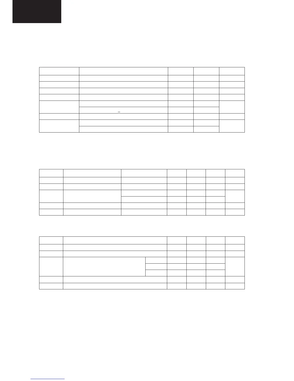
Parameter Conditions Min. Max. Unit
VIN to PGND 28 V
VCC to AGND AGND = PGND 6 V
BOOT to PGND 35 V
BOOT to SW -0.3 6.0 V
Continuous -0.5 24.0
SW to PGND
Transient (t < 20ns, f <
600KHz) -5.0 30.0
V
All other pins -0.3 V
CC
Human Body Model, JEDEC JESD22-A114 2.0
ESD
Charged Device Model, JEDEC JESD22-C101 2.5
kV
Recommended Operating Conditions
The Recommended Operating Conditions table defines the conditions for actual device operation. Recommended
operating conditions are specified to ensure optimal performance to the datasheet specifications. Fairchild does not
recommend exceeding them or designing to absolute maximum ratings.
Symbol Parameter Conditions Min. Typ. Max. Unit
V
CC
Bias Voltage VCC to AGND 4.5 5.0 5.5 V
V
IN
Supply Voltage VIN to PGND 3 24 V
FAN2106MPX -10 +85
T
A
Ambient Temperature
FAN2106EMPX -40 +85
°C
T
J
Junction Temperature +125 °C
f
SW
Switching Frequency 200 600 KHz
Thermal Information
Symbol Parameter Min. Typ. Max. Unit
T
STG
Storage Temperature -65 +150 °C
T
L
Lead Soldering Temperature, 10 Seconds +300 °C
P1 (Q2) 4
P2 (Q1) 7
T
JC
Thermal Resistance: Junction-to-Case
P3 4
°C/W
T
J-PCB
Thermal Resistance: Junction-to-Mounting Surface 35
(1)
Note:
1. Typical thermal resistance when mounted on a four-layer, two-ounce PCB, as shown in Figure 26. Actual results
are dependent on mounting method and surface related to the design.
34
LC-32LE340/343
LC-40LE340/343