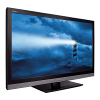
Do you have a question about the Sharp LC-32LE350M and is the answer not in the manual?
Guidelines for qualified service technicians regarding safety checks and servicing procedures.
Checks for safety before returning the receiver to the user, focusing on fire and shock hazards.
Importance of safety-related characteristics in components and proper part replacement.
Information on the use of lead-free solder and its associated symbols on PWBs and manuals.
Guidance on using lead-free wire solder for repairs to avoid damage or accidents.
Guidelines and precautions for soldering with lead-free solder, including tip maintenance.
Lists key service parts including PWB units, other units, and ICs for exclusive service use.
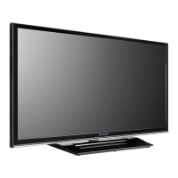
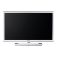
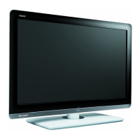
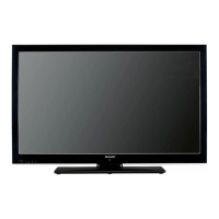
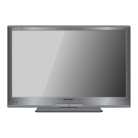
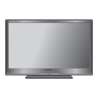
Details on screen size, resolution, video systems, audio, terminals, power, dimensions, and operating temperature.
Identification of controls, indicators, and connection terminals on the TV's front and rear panels.
Explanation of the functions for each button on the remote control unit.
Step-by-step instructions for safely attaching or detaching the TV stand.
Diagrams illustrating the physical dimensions of the TV unit in millimeters.
Step-by-step instructions for removing the rear cabinet assembly and stand.
Instructions for removing the bottom bracket and the left/right speakers.
Detailed steps for detaching the LCD panel module, including lock hook procedures.
Steps to enter/exit adjustment mode, controller key operations, and software upgrading.
Procedures for inputting EDID data for HDMI and Analog PC connections.
Guidelines for picture adjustment using Component and PC-RGB signals.
Procedures for performing manual and automatic white balance adjustments.
Steps for setting the TV to its original factory default configuration.
Explanation of the Smart Loader function for replicating TV settings via USB.
Instructions on how to start, exit, and manage public mode settings.
Details on various setting items available within the Public Mode menu.
Settings related to On Screen Display, Blue Screen, Input Mode, and RS-232C power control.
Configuration options for the remote control signal path through the TV.
Flowchart for diagnosing and resolving issues related to no power or no startup.
Flowchart for diagnosing no video issues when using RF signal input.
Flowchart for diagnosing no video issues with AV and Component signal inputs.
Flowchart for diagnosing no video issues with Component and HDMI signal inputs.
Flowchart for diagnosing no audio issues when using RF signal input.
Flowchart for diagnosing no audio issues with AV and Component signal inputs.
Flowchart for diagnosing no audio issues with HDMI signal input.
Flowchart for diagnosing no audio issues with HDMI analog audio input.
Visual representation of the TV's system architecture and component interconnections.
Component layout diagram for the Main Unit PCB, A-Chip view.
Component layout diagram for the Main Unit PCB, B-Symbol view.
Component layout diagram for the LED_IR Unit PCB.
Component layout diagram for the LED B Unit PCB.
Guidelines for interpreting schematic symbols, component ratings, and important safety notes.
Circuit diagram detailing the tuner module and its connections.
Further circuit details and component values for the tuner section.
Circuit diagram illustrating the HDMI input terminals and associated circuitry.
Further circuit details and component values for the HDMI terminal section.
Circuit diagram for PC audio input and USB connection terminals.
Further circuit details and component values for main terminal connections.
Circuit diagram for various video input interfaces.
Further circuit details and component values for video input sections.
Circuit diagram detailing the Digital Display Interface (DDI) connections.
Circuit diagram illustrating the DDR memory interface and connections.
Circuit diagram showing the flash memory interface.
Further circuit details and component values for the flash memory interface.
Circuit diagram for the connection to the LCD panel.
Further circuit details and component values for the panel interface.
Circuit diagram for the audio amplifier circuitry.
Further circuit details and component values for the audio amplifier.
Circuit diagram detailing the power supply unit and its components.
Further circuit details and component values for the power supply unit.
Circuit diagram for the TV's key inputs and remote control interface.
Further circuit details and component values for key and remote control interfaces.
List of sections covered in the Sharp Parts Guide.
List of parts for the various printed wiring boards.
List of capacitors used in the main unit assembly.
List of integrated circuits and diodes used in the main unit assembly.
List of resistors used in the main unit assembly.
Additional list of resistors for the main unit assembly.
List of tuners, connectors, and other components for the main unit.
List of components specifically related to the LCD panel assembly.
List and description of accessories supplied with the TV.
List of packing materials and items not intended for replacement.
Additional information on packing parts for the TV.
| Screen Size | 32 inches |
|---|---|
| Resolution | 1366 x 768 |
| Display Type | LCD |
| HDMI Ports | 2 |
| USB Ports | 1 |
| Refresh Rate | 50Hz |
| Backlight | LED |
| Aspect Ratio | 16:9 |
| Built-in Speakers | Yes |
| Audio Output | 10 W |



 Loading...