– 13 –
MD-MT866H/MD-MT866W
REMOVING AND REINSTALLING THE MAIN PARTS
Remove the mechanism according to the disassembling meth-
ods 1 to 4. (See Page 12.)
Figure 13-1
Figure 13-2
Figure 13-3
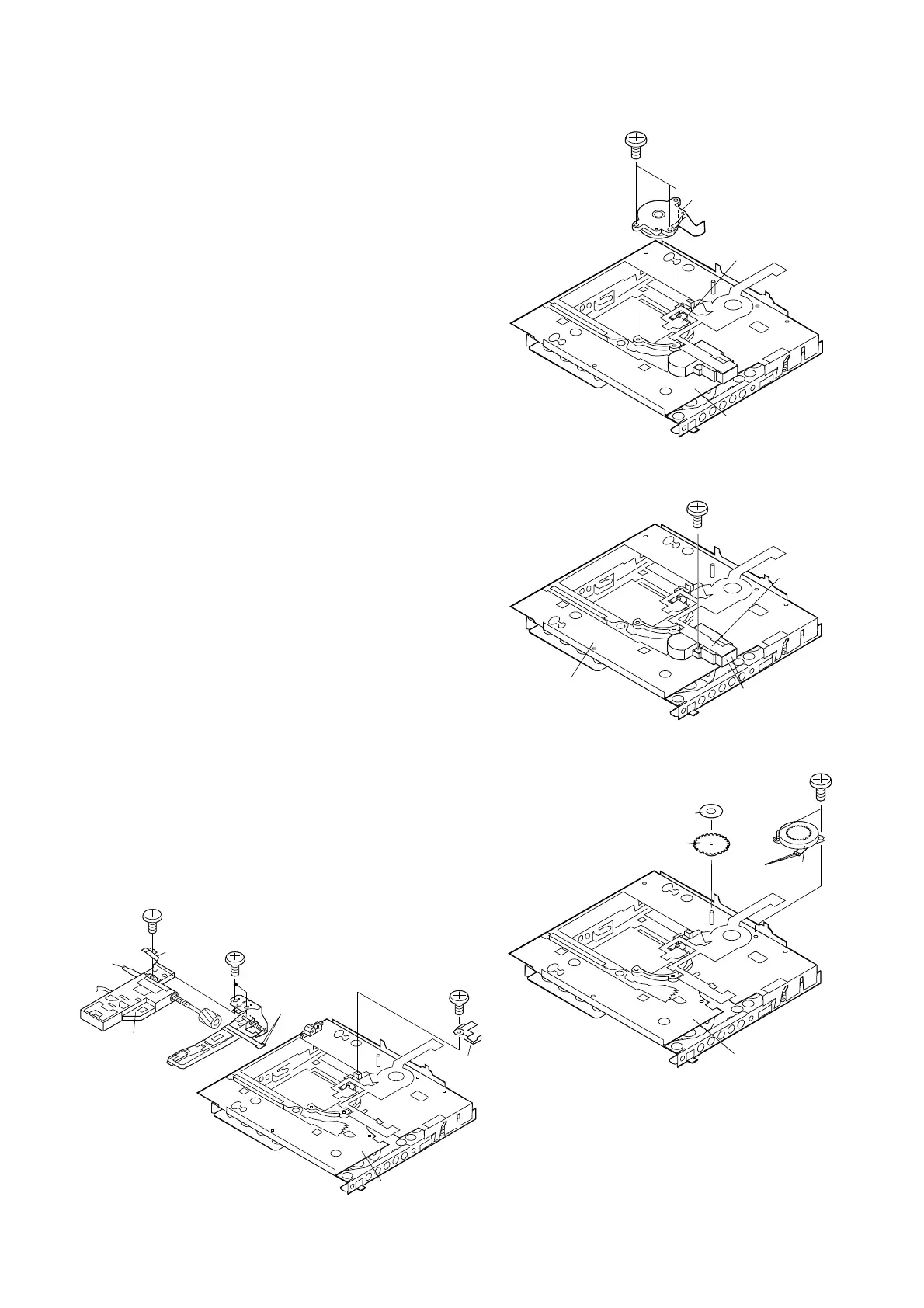
How to reinstall the optical pickup
(See Fig. 13-4.)
1. Remove the screw (E1) x 1 pc., and remove the grip spring.
2. Remove the screw (E2) x 1 pc. to remove the thrust
spring, and remove the drive screw and the optical
pickup from MD mechanism.
Then, remove the drive screw from the optical pickup.
How to remove the magnetic head (See Fig. 13-4.)
1. Remove the screws (D1) x 2 pcs. of the magnetic head and
the optical pickup, and remove the soldering (D3) x 2 pcs.
of the head flexible plate.
Note:
Mount carefully so as not to damage the magnetic head.
Figure 13-4
How to remove the Lift motor (See Fig. 13-2.)
1. Remove the solder joints (B1) x 2 of lift motor lead wire.
2. Remove the screw (B2) x 1 pc., and remove the lift motor.
Note:
Take care so that the motor gear is not damaged.
(If the gear is damaged, noise is caused.)
How to remove the sled motor (See Fig. 13-3.)
1. Remove the stop washer (C1) x 1 pc., and remove the drive
gear (C2) x 1 pc.
2. Remove the screws (C3) x 2 pcs.
3. Remove the solder joints (C4) x 3 of flexible PWB., and
remove the sled motor.
Note:
Take care so that the motor gear is not damaged.
(If the gear is damaged, noise is caused.)
How to remove the spindle motor (See Fig. 13-1.)
1. Remove the solder joints (A1) x 4 of flexible PWB.
2. Remove the screws (A2) x 3 pcs., and remove the spindle
motor.
(A2)x3
ø1.4x3mm
MD Mechanism
Spindle Motor
Solder Joints
(A1)x4
(B2)x1
ø1.4x3.8mm
MD Mechanism
Solder Joints
(B1)x2
Lift
Motor
MD Mechanism
(C1)x1
(C2)x1
(C3)x2
ø1.4x1.2mm
Sled
Motor
Solder
Joints
(C4)x3
(E1)x1
ø1.4x1.8mm
(D3)x2
Solder Joints
MD Mechanism
(E2)x1
ø1.4x1.8mm
Grip
Spring
(D1)x2
ø1.4x1.8mm
Optical Pickup
Drive
Screw
Thrust
Spring