Do you have a question about the Sharp MX-M264U and is the answer not in the manual?
Essential safety and handling guidelines for technicians performing service.
Critical warnings related to electrical shock, heat, and potential machine damage.
Guidelines for appropriate machine placement to ensure proper operation and ventilation.
Precautions to prevent static electricity damage to sensitive components during handling.
Specific instructions and safety notes for handling the Laser Scanner Unit (LSU).
Precautions for handling critical imaging components to maintain quality and prevent damage.
Specifies torque values for various screw types to ensure proper assembly and prevent loosening.
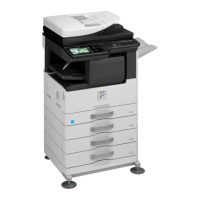
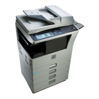
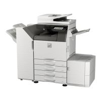
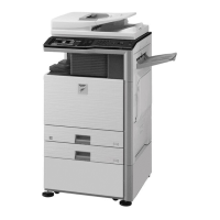
Overview of the machine's main components and their interconnections.
Lists available optional equipment and their compatibility with different models.
Key technical specifications including engine, scanner, and feeder details.
Performance data detailing print/copy speeds for different models and paper types.
Defines the maximum printable dimensions for various paper sizes supported by the machine.
Details the copy and print resolution capabilities, including bit depth and dither methods.
Specifications for scanner resolution, gradation, exposure, and document handling.
Information on the Automatic Document Feeder (ADF) capabilities, scan speed, and setup.
Details on paper handling, tray capacities, paper size/type support, and loading capacity.
Specifications for paper output locations, capacities, shifter functions, and dischargeable sizes.
Electrical power requirements, energy consumption rates, and TEC values.
Physical size and weight specifications of the machine, including installed options.
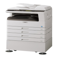
Illustrates the machine's external components and their locations with numbered labels.
Identifies major internal components like toner cartridge and fusing unit and their functions.
Details the ADF feeding mechanism, original guides, and the document glass.
Identifies and explains the function of various external connectors like LAN, USB, and phone jacks.
Describes the function of each key, indicator, and the touch panel on the control panel.
Details sensors, detectors, motors, and PWBs within the Reversing Single Pass Feeder (RSPF).
Lists and describes the function of various rollers within the RSPF for paper transport.
Lists and describes the function of various sensors used in the machine for detection.
Identifies various switches like door switches and the main power switch and their functions.
Lists solenoids and clutches and their operational functions in paper transport and gate control.
Identifies drive motors for scanner, paper exit, ADU, and toner supply.
Lists lamps used in the machine, such as copy lamp and heater lamp, and their functions.
Identifies cooling fans for fusing and power supply, and ozone filters.
Lists the various Printed Wiring Boards (PWBs) and their functions, such as scanner and PCU.
Lists and describes the function of various rollers throughout the paper path.
Explains how to perform adjustments and the importance of following the sequence.
Comprehensive list of adjustable parameters, their job numbers, and simulation references.
Step-by-step procedures for performing specific adjustments like developing unit and high voltage.
Explains the functions and benefits of the simulation mode for service technicians.
Provides detailed steps on how to enter and operate the simulation mode using the control panel.
A comprehensive list of simulation codes, their functions, and related sections for diagnostics.
General information on error display, function, message types, and self-diagnostic procedures.
Outlines the sequence of operations and their status during various machine troubles.
Detailed listing of error codes, their causes, detection mechanisms, and countermeasures.
Specific explanations of common error codes and the steps required for resolution.
Lists various JAM codes for main unit, finisher, and RSPF, along with their causes and remedies.
Explains the structure and meaning of communication report codes for image sending and FAX.
Information on dial tone detection settings and troubleshooting for facsimile communication.
Explains when firmware updates are needed and general notes on ROM compatibility.
Details methods for updating firmware using SIM 49-1, FTP, Web page, and CN update function.
Lists maintenance items, their recommended intervals, and actions (clean, replace, lubricate).
Information on related items such as counter clearing procedures for various components.
Step-by-step instructions for disassembling and assembling the drum and drum section.
Instructions for disassembling and assembling the developer, toner filter, DV blade, and toner sensor.
Procedures for disassembling and assembling fusing unit components like thermostat, thermistor, and rollers.
Steps for disassembling and cleaning optical components such as table glass, scanner lamp, and CCD.
Detailed instructions for disassembling and reassembling paper feed mechanisms for various trays.
Procedures for disassembling and assembling the side door unit components like transport rollers.
Steps for disassembling and removing the 1st paper exit unit components like cooling fan and rollers.
Instructions for safely removing the Laser Scanner Unit (LSU) without disassembling it.
Procedures for removing the power source unit, including disconnecting connectors.
Details on removing and replacing various Printed Wiring Boards (PWBs) like SCN, PCU, and MFPC.
Instructions for removing and replacing the ozone filter located in the machine.
Procedures for disassembling transport rollers within the paper transport section.
Steps for disassembling the operation panel unit, USB I/F, KEY PWB, and LVDS PWB.
Instructions for disassembling and removing the RSPF unit and its sub-components.
Visual representation of HDD and SD card partitions and data storage layout.
Lists the types of data stored on the HDD and their corresponding file systems and notes.
Details the data stored on the SD card for different configurations (HDD installed/uninstalled).
Outlines procedures for replacing MFPC PWB, HDD, and SD card, including data backup.
Detailed steps for HDD replacement, covering data backup and reinstallation.
Steps for backing up and replacing the SD card, including firmware upgrades and data restoration.
Overview of functions available on the Hidden Web Page for serviceman access.
Guides on accessing the Hidden Web Page and its primary features like password setting.
Step-by-step instructions to access the service web page via a web browser.
Procedure for changing the service web page password to enhance security.
How to print system settings and test pages via the web interface for verification.
Procedure for downloading fonts, forms, and macros to the machine's HDD.
Functionality to import/export system settings for efficient machine configuration and replication.
Procedures for backing up and restoring document filing data using export and import functions.
Accessing user management settings like password and login via the web interface.
Configuring pages limit and favorite operation groups for user management.
Functions for saving and viewing the machine's job log for operational analysis.
Steps to update the machine's firmware using the web interface for performance enhancements.
Functions for acquiring and managing system logs for troubleshooting and issue diagnosis.
Configuration options for the Field Support System, including proxy and polling settings.
High-level system block diagram illustrating major units and their interconnections.
Detailed wiring diagram showing connections to the PCU PWB.
Comprehensive block diagram of the MFP control PWB connections and interfaces.
Wiring diagram illustrating connections for the Scanner control PWB.
Wiring details for the operation panel components, including LCD, touch panel, and key PWB.
Block diagram illustrating the FAX unit's main components, interfaces, and connections.
Diagram showing the DC power distribution within the machine to various units.
Comprehensive list of signals, their functions, PWB locations, and pin assignments.
Lists specific tools and part codes required for maintenance and repair procedures.
| Functions | Print, Copy, Scan, Fax |
|---|---|
| Print Resolution | 600 x 600 dpi |
| Copy Resolution | 600 x 600 dpi |
| Scan Resolution | 600 x 600 dpi |
| Paper Capacity | 250 sheets |
| Duplex Printing | Yes |
| Network Connectivity | Ethernet, USB |
| Operating System Compatibility | Windows, Mac |
| Display | LCD |
| Type | Multifunction / All-in-One |
| Print Speed | 26 pages per minute |
| Copy Speed | 26 cpm |
| Fax Resolution | 300 x 300 dpi |