MX-M316N SIMULATION 6 – 60
50-27
Purpose
Adjustment
Function (Purpose)
Used to perform the image loss adjustment
of scanned images in the FAX or image
send mode.
Section
Operation/Procedure
1) Select a target adjustment mode with [FAX] or [SCANNER]
key.
2) Select an adjustment target item with scroll key on the touch
panel.
3) Enter the set value with 10-key.
4) Press [OK] key. (The set value is saved.)
A-I: When the adjustment value is increased, the image loss is increased.
1step = 0.1mm
50-28
Purpose
Adjustment
Function (Purpose)
Used to automatically adjust the image
loss, void area, image off-center, and image
magnification ratio.
Section
Operation/Procedure
The following adjustment items can be executed automatically with
SIM50-28.
* ADJ 12 Print image position, image magnification ratio, void
area, off-center adjustments (Manual adjustments)
* ADJ 13 Scan image magnification ratio adjustment (Manual
adjustment)
* ADJ 14 Scan image off-center adjustment (Manual adjustment)
* ADJ 15 Used to adjust the copy image position and the image
loss (Manual adjustments)
1) Select an adjustment item with the menu button.
2) Press [EXECUTE] key, and the adjustment pattern is printed.
3) Set the adjustment pattern on the document table.
4) Press [EXECUTE] key, and the adjustment pattern is scanned.
5) Press [OK] key.
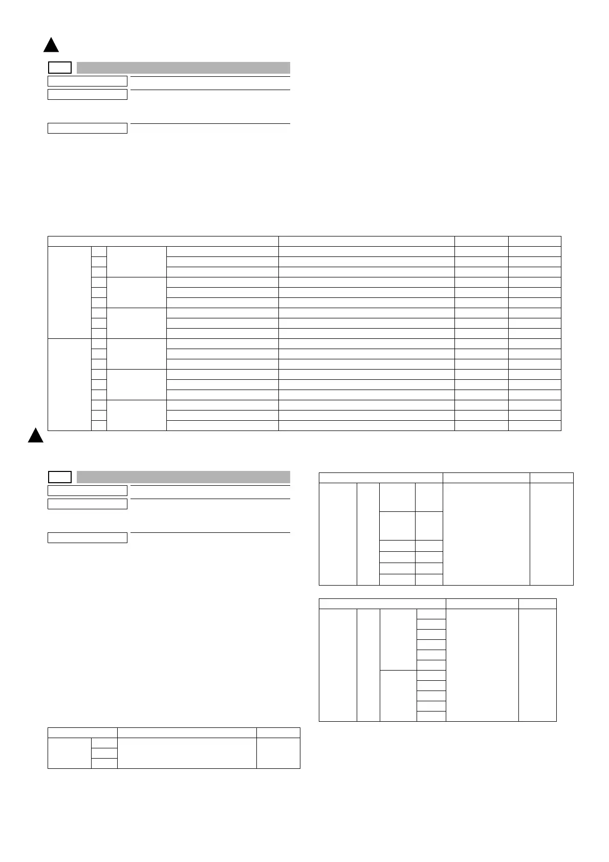
Item/Display Content Setting range Default value
FAX send A Image loss
amount setting
OC
LEAD_EDGE (OC) OC lead edge image loss amount setting 0 - 100 30 (3mm)
B FRONT_REAR (OC) OC side image loss amount setting 0 - 100 20 (2mm)
C TRAIL_EDGE (OC) OC rear edge image loss amount setting 0 - 100 20 (2mm)
D Image loss
amount setting
SPF SIDE1
LEAD_EDGE (SPF_SIDE1) Front surface lead edge image loss amount setting 0 - 100 20 (2mm)
E FRONT_REAR (SPF_SIDE1) Front surface side image loss amount setting 0 - 100 20 (2mm)
F TRAIL_EDGE (SPF_SIDE1) Front surface rear edge image loss amount setting 0 - 100 30 (3mm)
G Image loss
amount setting
SPF SIDE2
LEAD_EDGE (SPF_SIDE2) Back surface lead edge image loss amount setting 0 - 100 20 (2mm)
H FRONT_REAR (SPF_SIDE2) Back surface side image loss amount setting 0 - 100 20 (2mm)
I TRAIL_EDGE (SPF_SIDE2) Back surface rear edge image loss amount setting 0 - 100 30 (3mm)
When
image
send mode
(Except for
FAX and
copy)
A Image loss
amount setting
OC
LEAD_EDGE (OC) OC lead edge image loss amount setting 0 - 100 0 (0mm)
B FRONT_REAR(OC) OC side image loss amount setting 0 - 100 0 (0mm)
C TRAIL_EDGE(OC) OC rear edge image loss amount setting 0 - 100 0 (0mm)
D Image loss
amount setting
SPF SIDE1
LEAD_EDGE (SPF_SIDE1) Front surface lead edge image loss amount setting 0 - 100 0 (0mm)
E FRONT_REAR (SPF_SIDE1) Front surface side image loss amount setting 0 - 100 0 (0mm)
F TRAIL_EDGE(SPF_SIDE1) Front surface rear edge image loss amount setting 0 - 100 0 (0mm)
G Image loss
amount setting
SPF SIDE2
LEAD_EDGE (SPF_SIDE2) Back surface lead edge image loss amount setting 0 - 100 0 (0mm)
H FRONT_REAR (SPF_SIDE2) Back surface side image loss amount setting 0 - 100 0 (0mm)
I TRAIL_EDGE(SPF_SIDE2) Back surface rear edge image loss amount setting 0 - 100 0 (0mm)
Item/Display Content Section
OC ADJ MFT Document lead edge
Document off-center
Sub scanning magnification ratio
Scanner
CS1
CS2
Item/Display Content Section
SPF ADJ
(RSPF)
ALL SIDE1
(Front
surface)
MFT Document lead edge
Document off-center
Sub scanning
magnification ratio
Scanner
SIDE2
(Back
surface)
CS1
CS2
MFT
CS1
CS2
Item/Display Content Section
SETUP/
PRINT
ADJ
ALL LEAD MFT Print off center
Print lead edge
Engine
CS1
CS2
ADU
CS3
CS4
OFF
SET
MFT
CS1
CS2
ADU
CS3
1
: ‘15/Aug.
1