FOR
A
COMPLETE
DESCRIPTION
OF
THE
OPERATION
OF
THIS
UNIT,
PLEASE
REFER
TO
THE
OPERATION MANUAL.
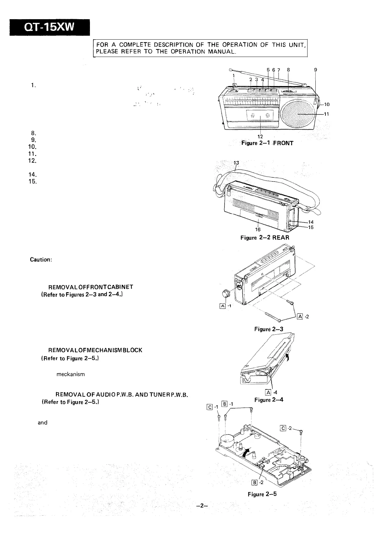
NAMES OF PARTS
1.
Volume Control
.,’
2. Stop/Eject Button
.,
I
..
:,‘.
>.
;‘
-
. .
:
3. Fast Forward Button
4. Rewind Button
i.
::
:,
,_..
5. Play Button
6. Record Button
7. Telescopic Rod Antenna
8.
Mode Selector
9. Built-in Microphone
IO.
Tuning Control
11.
Speaker
12.
Cassette Compartment
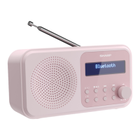
13. Carrying Belt
14.
Earphone Jack
15.
External DC Power Input Jack
16. Battery Compartment
Figure
2-2
REAR
DISASSEMBLY
Caution:
Prior to the disassembly, be sure to remove the AC adaptor,
battery and cassette tape from the unit.
q
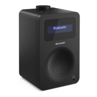
REMOVAL
OF
FRONT
CABINET
(Refer
to
Figures
2-3
and
Z-4.)
1. Remove the tuning control knob.
2. Remove five screws from the rear cabinet. (Two of them
are in the battery case.)
3. Push the stop/eject button to open the cassette holder.
4. Withdraw the front cabinet by holding its both sides.
At this time, disconnect two lead wires from the speaker.
Figure
2-3
q
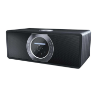
REMOVAL
OF
MECHANISM BLOCK
(Refer
to
Figure
2-5.)
1. Remove two screws from the mechanism block and draw
out the meckanism block.
2. Disconnect one socket from the audio P.W.B.
q
REMOVAL
OF
AUDIO
P.W.B.
AND TUNER
P.W.B.
(Refer
to
Figure
2-5.)
1. Remove one screw from the audio P.W.B.
2. Romove one screw from the frame. Then the audio P.W.B.
and
tuner P.W.B. can be removed from the rear cabinet.
la4
Figure
2-4
Figure
2-5