MECHANICAL ADJUSTMENT
TORQUE
CHECK
AT PLAY,
FAST
FORWARD AND
REWIND
MODES
(See
Table
3.)
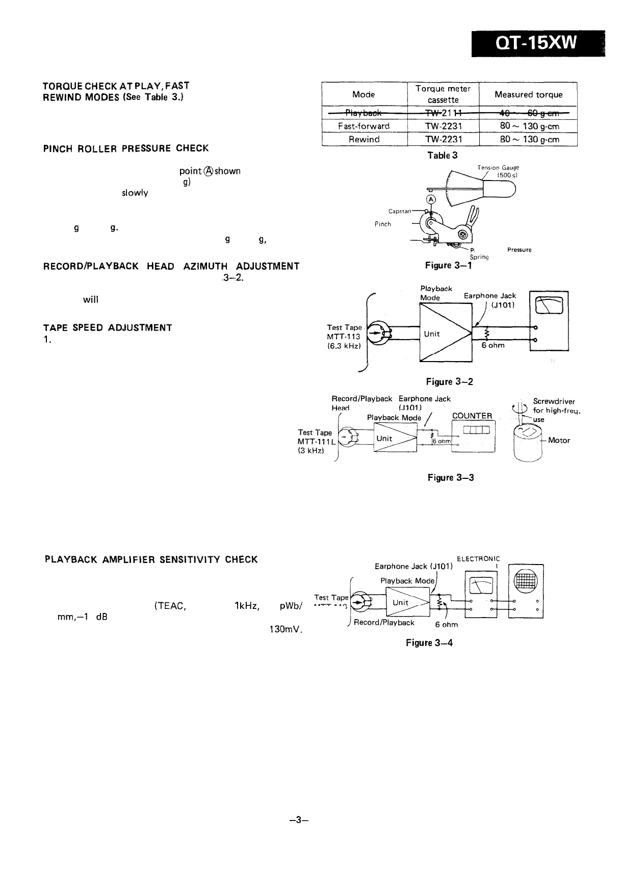
Put a
torque
meter cassette in the cassette holder of the unit,
and see that the measured torque in each mode is normal as
shown in Table 3.
PINCH
ROLLER
PRESSURE
CHECK
1. Place the unit in playback mode.
Table
3
2. Push the pinch roller, at the
point@shown
in Figure 3-1,
by using a tension gauge (500
g)
so that it will come off the
capstan. Then,
slowly
release the tension until the pinch
roller hits the capstan again (i.e., the pinch roller is about to
rotate again). Check, then, the tension gauge is reading
300
g
to 400
g.
Pfnch
Roller
3. If the reading is outside the range of 300
g
to 400
g,
replace
the pressure spring of the pinch roller.
inch Roller
Pressure
swng
RECORD/PLAYBACK HEAD AZIMUTH ADJUSTMENT
1. Connect instruments as shown in Figure
.3-2.
2. Adjust the head azimuth adjusting screw so that the output
signal
will
have maximum waveform.
Figure
3-l
ELECTRONIC
VOLTMETER
TAPE
SPEED
ADJUSTMENT
1.
Connect instruments as shown in Figure 3-3.
2. Put a screwdriver (for high-frequency use) into the hole of
the motor, and adjust the variable resistor so that the
output frequency is 2955 Hz to 2980 Hz on frequency
counter.
Record/Playback
Head
Figure
3-2
FREQUENCY
Figure
3-3
ELECTRICAL ADJUSTMENT
PLAYBACK AMPLIFIER
SENSITIVITY
CHECK
1. Connect instruments as shown in Figure 3-4.
2. Set the mode selector switch at tape, the volume control
knob at max.
ELECTRONIC
OSCILLOSCOPE
01)
VOLTMETER
3. Playback a test tape
(TEAC,
MTT-118,
1
kHz,
250
pWb/
MTT-118
mm,-1
0
d8
prerecorded).
4. See that the electronic voltmeter is reading about
130mV.
Head
Figure
3-4
-3-