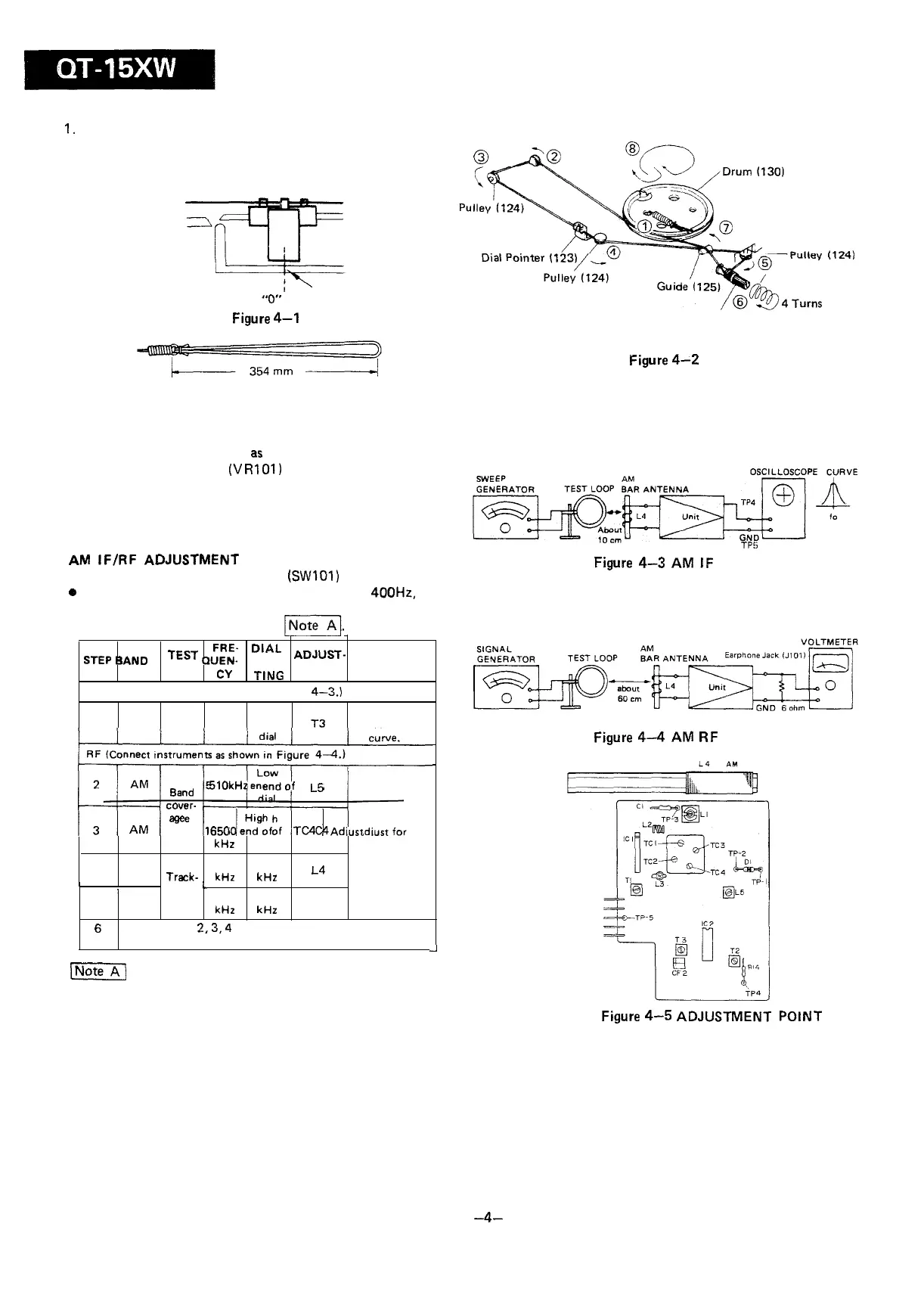
DIAL CORD STRINGING
1.
Turn the drum fully clockwise and stretch its cord over the
parts in the numerical order as shown in Figure 4-2.
2. Turn the tuning control shaft fully counterclockwise and
fix its pointer to “0” point as shown in Figure 4-l.
“0”
Point
Figure
4-l
Tuning Control
Shaft (128)
Figure
4-Z
GENERAL ADJUSTMENT INSTRUCTION
Should it become necessary at any time to check the adjust-
ment of this receiver, proceed
as
follows;
1. Set the volume control (V
R
101)
to maximum.
2. Attenuate the signals from the generator enough to swing
the most sensitive range of the output meter.
3. Use a non-metallic adjustment tool.
4. Repeat adjustments to insure good results.
AM
IF/RF
ADJUSTMENT
l
Set the mode selector switch
(SWIOI)
to AM position.
o
Set the signal generator to produce a signal of
400Hz,
30%.
AM modulated.
.
For adjustment in step 4, see
/NoteA].
TEST
QUEN- SET-
FRE-
D’AL
ADJUST-
STEP
BAND
STAGE
Cy
MENT
REMARKS
TING
IF (Connect instruments as shown in Figure
4-3.)
High
Adjust for
1
AM IF
455kHz end of T3
best IF
dial
CUNe.
RF (Connect instruments as shown in Figure
4-4.)
RF (Connect instruments as shown in Figure
4-4.)
Low
2
AM
6and
5lOkHz
endof
L6
dial
CO”I?r-
I 3 I
AM
I
age
I 1660
IeEEf
I
TC4
I
Adiust
for
kHz
dial
maximum
4
AM
600
600
output.
Track-
kHz kHz
L4
/
ing
L
5 AM
1400 1400
kHz
kHz
TC3
6
Repeat
steps
2,3,4
and 5 until
no further
improvement
can be made.
-.
[NoteA]
Check the alignment of the receiver antenna coil by
bringing a piece of ferrite (such as a coil slug) near the antenna
loop stick, then a piece of brass. If ferrite increases output,
loop requires more inductance. If brass increases output, loop
requires less inductance. Change loop inductance by sliding the
bobbin toward the center of ferrite core to increase inductance,
or to decrease inductance.
Figure
4-3
AM IF
TP5
ELECTRONIC
Figure
4-4
AM
RF
Figure
4-5
ADJUSTMENT POINT
-4-