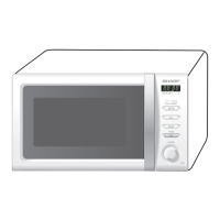
R239(W)
9 – 1
R239(W)
Service Manual
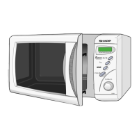
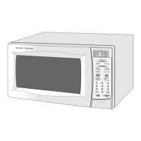
CHAPTER 9. TOUCH CONTROL PANEL ASSEMBLY
[1] OUTLINE OF TOUCH CONTROL PANEL
The touch control section consists of the following units as shown in
the touch control panel circuit.
(1) Switch Unit (2) Control Unit
The principal functions of these units and their related signals are
explained below.
1. Switch Unit
The switch unit is composed of a matrix, signals generated in the LSI
are sent to the switch unit through P25 and P33. When a button is
pressed, a signal is completed through the switch unit and passed
back to the LSI through P50 and P52 to perform the function that was
requested. When the jog dial is rotated, the encoder converts the sig-
nal from the power source circuit into the pulse signal, and the pulse
signal is sent to the LSI through P31 and P32.
2. Control Unit
Control unit consists of LSI, reset circuit, indicator circuit, power
source circuit, relay circuit, buzzer circuit and synchronizing signal cir-
cuit.
1) Reset Circuit
This circuit generates a signal which resets the LSI to the initial
state when power is supplied.
2) Indicator Circuit
This circuit consists of 4-digits, 12-segments and 3-common elec-
trodes using a Liquid Crystal Display.
3) Power Source Circuit
This circuit generates voltage necessary in the control unit from the
AC line voltage. In addition, the synchronizing signal is available in
order to compose a basic standard time in the clock circuit.
4) Relay Circuit
To drive the magnetron, fan motor, turntable motor and light the
oven lamp.
5) Buzzer Circuit
The buzzer is responsive to signals from the LSI to emit audible
sounds (switch unit touch sound and completion sound).
6) Synchronizing Signal Circuit
The power source synchronizing signal is available in order to com-
pose a basic standard time in the clock circuit. It accompanies a
very small error because it works on commercial frequency.
7) 2nd. Interlock Relay Control Switch
A switch to “tell” the LSI if the door is open or closed.
8) Back Light Circuit
A circuit to drive the back light (Light emitting diodes LD1 - LD4).
[2] DESCRIPTION OF LSI
The I/O signal of the LSI are detailed in the following table.
Symbol Voltage Application
VSS -5V LSI(IC1)
Pin No. Signal I/O Description
1P50IN
Signal coming from switch unit.
When either H6 line on switch unit matrix is touched, a corresponding signal out of P25 and P33 will be input
into P50. When no button is pressed, the signal is held at “H” level.
2 P51 IN Connected to GND.
3P52IN
Signal similar to P50.
When either H5 line on switch unit matrix is touched, a corresponding signal will be input into P52.
4 P53 IN Connected to GND.
5 IC IN Connected to VSS.
6 XT1 IN Connected to VSS.
7 XT2 Terminal not used.
8VDDIN
Power source voltage input terminal.
The power source voltage to drive the LSI. Connected to GND.
9 VSS IN
Power source voltage input terminal.
The power source voltage to drive the LSI.
10 X1 IN
Internal clock oscillation frequency input setting.
The internal clock frequency is set by inserting the resistor-capacitor oscillation circuit with respect to X2 termi-
nal.
11 X2 OUT
Internal clock oscillation frequency control output.
Output to control oscillation input of X1.
12 RESET IN
Auto clear terminal.
Signal is input to reset the LSI to the initial state when power is applied.
13-15 P00-P02 OUT Terminal not used.
16 P03 OUT Back light circuit (Light emitting diodes) driving signal.
17 CAPH - Terminal not used.
18 CAPL - Terminal not used.
19-21 VLC0-VLC2 IN
Power source voltage input terminal.
Standard voltage for LCD.
22 COM0 OUT
Common data signal.
Connected to LCD signal C1.
23 COM1 OUT
Common data signal.
Connected to LCD signal C2.
24 COM2 OUT
Common data signal.
Connected to LCD signal C3.