10
R-244M -
HIGH
H : +5V
L : 0V
H : +5V
L : 0V
MEDIUM
HIGH
ON
ON
OFF
OFF OFF
24 sec.
8 sec.
A
B
0.1 sec.
2 sec.
H : +5V
L: 0V
H : +5V
L: 0V
20.0 msec
During cooking
H : +5V
L : 0V
20.0 msec
H : +5V
L : 0V
1-12 SEG0 - OUT Segment data signal.
SEG11 Connected to LCD.
The relation between signals are as follows:
LSI signal (Pin No.) LCD (Pin No.) LSI signal (Pin No.) LCD (Pin No.)
SEG 0 (1) ................................ S6 SEG 6 (7)........................... S12
SEG 1 (2) ................................ S7 SEG 7 (8)............................. S5
SEG 2 (3) ................................ S8 SEG 8 (9)............................. S4
SEG 3 (4) ................................ S9 SEG 9 (10)........................... S3
SEG 4 (5) .............................. S10 SEG 10 (11)......................... S2
SEG 5 (6) .............................. S11 SEG 11 (12)......................... S1
13 R60 OUT Tact switch strobe signal.
Signal applied to tact switch section. A pulse signal is input to R81 or R83 terminal
while the tact switch SW1 or SW8 is touched.
14 R61 OUT Tact switch strobe signal.
Signal applied to tact switch section. A pulse signal is input to R81or R83 terminal
while the tact switch SW2 or SW5 is touched.
15 R62 OUT Tact switch strobe signal.
Signal applied to tact switch section. A pulse signal is input to R81 or R83 terminal
while the tact switch SW3 or SW6 is touched.
16 R63 OUT Tact switch strobe signal.
Signal applied to tact switch section. A pulse signal is input to R81 or R83 terminal
while the tact switch SW4 or SW7 is touched.
17 AIN0 IN To input signal which communicates the door open/close information to LSI.
Door close "L" level signal (0V). Door open "H" level (+5V)
18-20 AIN1-AIN3 IN Terminal to change functions according to the Model.
By using the A/D converter contained in the LSI, DC voltage in accordance with the
Model in operation is applied to set up its function.
21 VSS IN Power source voltage: 0V.
VSS voltage of power source circuit input.
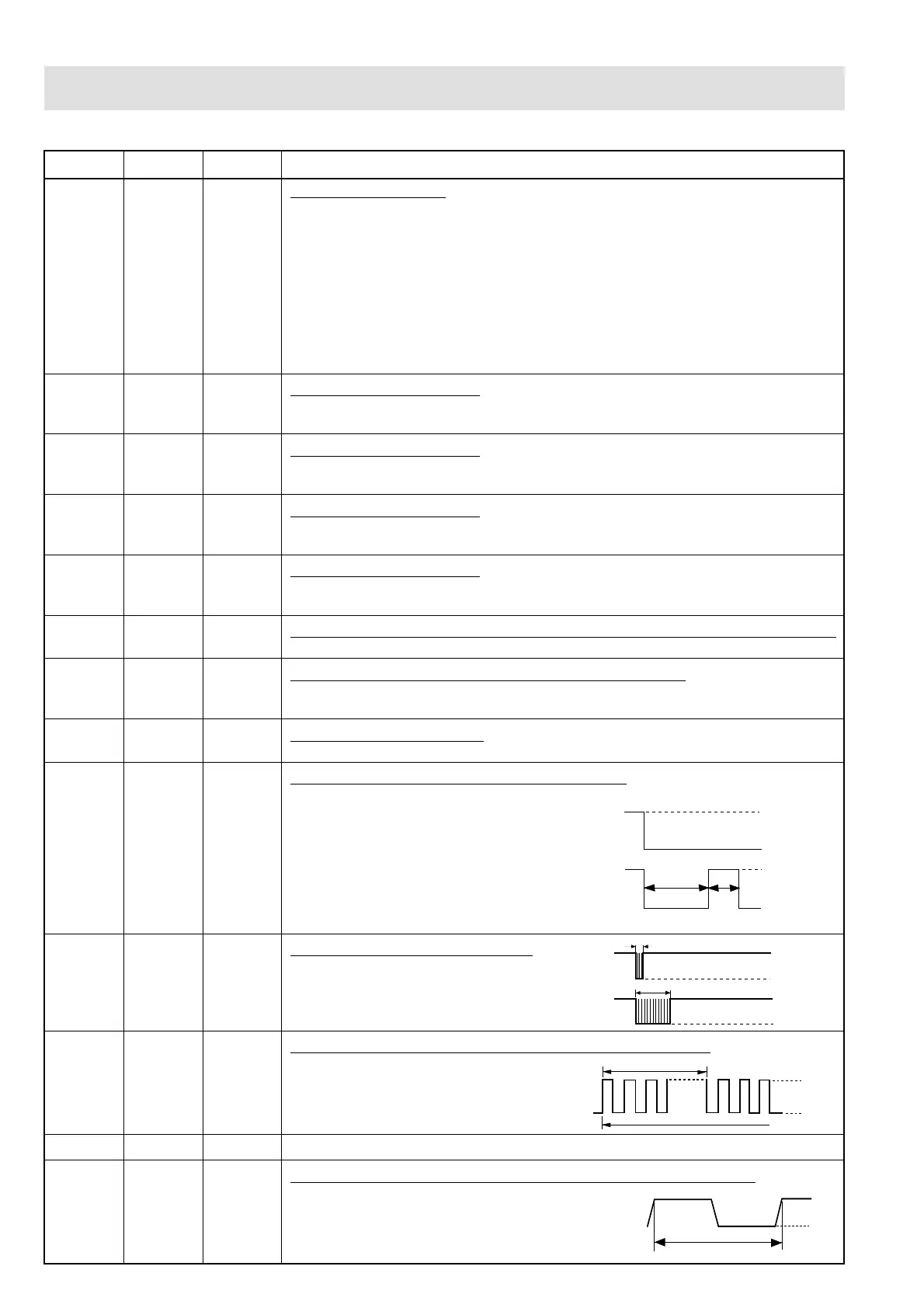
22 R70 OUT Magnetron high-voltage circuit driving signal.
To turn on and off the cook relay
(RY2). The signals holds "L" level
during microwave cooking and "H"
level while not cooking. In other cook-
ing modes (variable cooking) the sig-
nal turns to "H" level and "L" level in
repetition according to the power level.
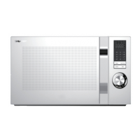
23 R71 OUT Signal to sound buzzer (2.0 kHz).
A: Tact switch touch sound.
B: Completion sound.
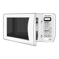
24 R72 OUT Oven lamp, fan motor and turntable motor driving signal.
To turn on and off shut off relay (RY1). The
square waveform voltage is delivered to
the RY1 driving circuit.
25 R73 IN Terminal not used.
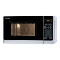
26 INT2 IN Signal synchronized with commercial power source frequency.
This is the basic timing for time processing of LSI.
DESCRIPTION OF LSI
LSI(IXA085DR)
The I/O signal of the LSI(IXA085DR) are detailed in the following table.
Pin No. Signal I/O Description