G
G watesJul 4, 2025
oven light failed. Does not come on any more
oven light failed. Does not come on any more
| Brand | Sharp |
|---|---|
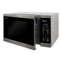
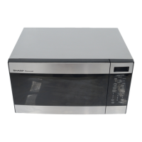
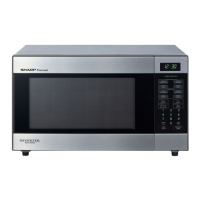
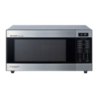
| Model | R-395N |
| Category | Microwave Oven |
| Language | English |
General guidance and safety information for service personnel.
Safety precautions regarding exposure to microwave radiation during servicing.
Critical warnings and conditions to ensure before operating or servicing the oven.
Procedural steps for safety checks before servicing internal components.
Specific warning and procedure for safely discharging the high-voltage capacitor.
Procedural steps for reassembly and functional checks after servicing.
Identification of external and internal parts of the microwave oven.
Detailed layout and function of the microwave oven's touch control panel.
Describes the initial state of the oven when powered on but not operating.
Explains the sequence and internal operations during high power cooking.
Details the automatic power reduction feature after extended high-power operation.
Explains the mechanical operation of the oven door opening system.
Describes the function and operation of door interlock safety switches.
Explains the role and operation of the monitor switch in the door safety circuit.
Details the function and potential causes of blown F10A fuse.
Introduction to the troubleshooting section and its methodology.
A troubleshooting chart correlating problems with possible causes and tests.
Procedure for testing the magnetron's continuity and output power.
Procedure for testing the continuity of the power transformer windings.
Procedure for testing the resistance of the high voltage rectifier assembly.
Procedure for testing the high voltage capacitor's continuity and leakage.
Procedure for testing the continuity of various switches.
Procedure for testing the oven's temperature fuse continuity.
Procedure for testing the resistance of fan and turntable motors.
Guidance on troubleshooting and replacing the F10A fuse.
Procedure for testing the noise filter's continuity.
Guidance on troubleshooting and replacing the high voltage fuse.
Procedure for testing the touch control panel and diagnosing unit failures.
Procedure for testing the key unit and determining if the control unit or keypad is faulty.
Procedure for testing the operation and voltage of relays RY1 and RY2.
Troubleshooting steps for an open foil pattern on the printed wiring board.
Overview of the touch control panel's constituent units and their functions.
Precautions and procedures for servicing the touch control panel unit.
Information on identifying and using lead-free solder for repairs.
Guidance on using lead-free wire solder and appropriate tools.
Techniques and precautions for soldering with lead-free solder.
Safety warnings and checks required before performing any component replacement.
Step-by-step instructions for safely removing the oven's outer casing.
Procedure for removing and reinstalling the power transformer.
Instructions for removing HV rectifier, fuse, and capacitor.
Detailed steps for safely removing the magnetron assembly.
Procedure for disconnecting positive lock connectors.
Steps for removing the control panel assembly from the oven.
Procedure for replacing the graphic sheet and membrane switch.
Instructions for removing the turntable motor.
Procedure for removing and reinstalling the cooling fan motor.
Steps for replacing the power supply cord.
Procedure for removing door interlock and monitor switches.
Instructions for adjusting door interlock and monitor switches for proper operation.
Detailed procedure for removing and replacing the oven door assembly.
Specifies the safety standard for microwave radiation emission limits.
Steps and materials needed for performing microwave leakage tests.
Electrical schematic diagram showing the oven's circuitry in off and on conditions.
Pictorial representation of component connections within the oven.
Detailed circuit diagram for the control unit, including key and LSI units.
Diagram showing the layout of components on the power unit's printed wiring board.