R -3A54
R-3E54
MAGNETRON REMOVAL
1. CARRY OUT3JCHECKS
5. Remove the magnetron from the waveguide with
2. Disconnect leads from magnetron.
3. Remove the two(2) screws holding air guide to the
magnetron and oven cavity. And remove the air
guide.
4. Carefully remove four(4) screws holding magnetron
to waveguide, when removing the screws hold the
magnetron to prevent it from falling.
care so the magnetron antenna is not hit by any
metal object around the antenna
CAUTION: WHEN REPLACING THE MAGNETRON,
BE SURE THE R.F. GASKET IS IN
PLACE AND THE MAGNETRON
MOUNTING SCREWS ARE TIGHTENED
SECURELY.
CONTROL PANEL REPLACEMENT
Removal
1. CARRY OUT 3D CHECKS.
2. Disconnect the leads from the control panel.
3. Remove the single screw holding the control panel
Installation
1. Put the tabs of the control panel into the holes of
to the oven cavity.
4. Lift up the control panel assembly.
5. Release the control panel from the oven cavity.
6. Now, the control panel assembly is free.
the oven cavity.
2. Push down the control panel.
3. Hold the control panel to the oven cavity with the
single( 1) screw.
4. Connect the leads to the control panel.
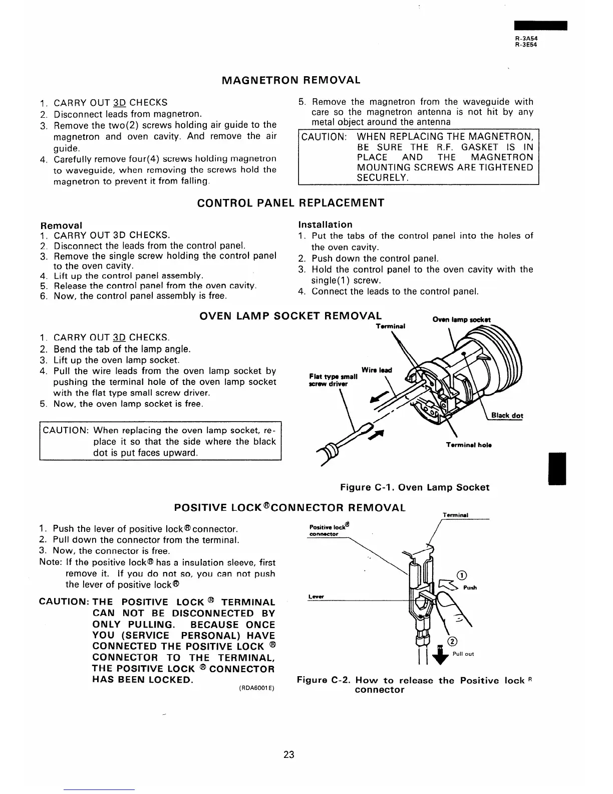
OVEN LAMP SOCKET REMOVAL
Own lamp scxkot
1. CARRY OUT 3D CHECKS.
2. Bend the tab of the lamp angle.
3. Lift up the oven lamp socket.
4. Pull the wire leads from the oven lamp socket by
pushing the terminal hole of the oven lamp socket
with the flat type small screw driver.
5. Now, the oven lamp socket is free.
CAUTION: When replacing the oven lamp socket, re-
place it so that the side where the black
dot is put faces upward.
Figure C-l. Oven Lamp Socket
POSITIVE LOCK@tONNECTOR REMOVAL
Terminal
1. Push the lever of positive IockQconnector.
2. Pull down the connector from the terminal.
3. Now, the connector is free.
Note: If the positive locka has a insulation sleeve, first
remove it.
If you do not so, you can not push
the lever of positive locka
CAUTION: THE POSITIVE LOCK @ TERMINAL
CAN NOT BE DISCONNECTED BY
ONLY PULLING.
BECAUSE ONCE
YOU (SERVICE PERSONAL) HAVE
CONNECTED THE POSITIVE LOCK @I
CONNECTOR TO THE TERMINAL,
THE POSITIVE LOCK a CONNECTOR
HAS BEEN LOCKED.
(R DA6001 E)
Positive lock’
Figure C-2. How to release the Positive lock R
connector
23