R-3A54
R-3E54
4.
5.
6.
7.
8.
Shut the door (close the contacts of latch
switches).
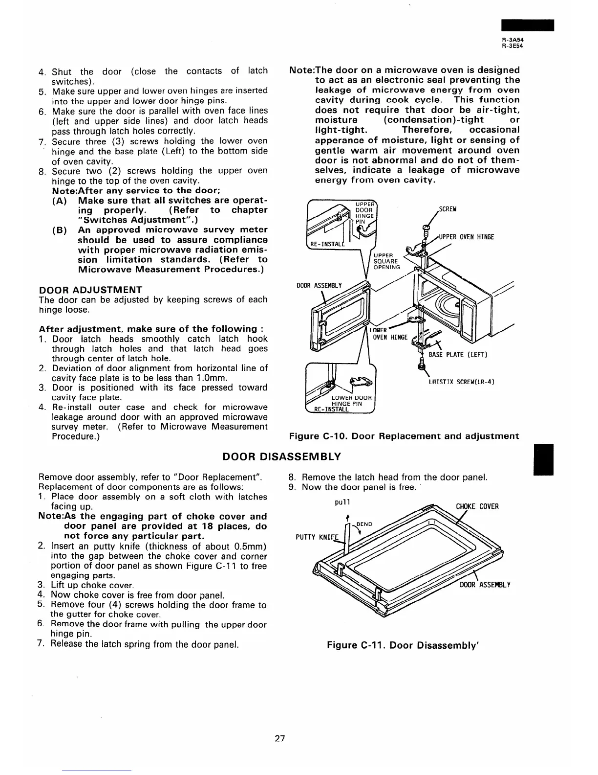
Make sure upper and lower oven hinges are inserted
into the upper and lower door hinge pins.
Make sure the door is parallel with oven face lines
(left and upper side lines) and door latch heads
pass through latch holes correctly.
Secure three (3) screws holding the lower oven
hinge and the base plate (Left) to the bottom side
of oven cavity.
Secure two (2) screws holding the upper oven
hinge to the top of the oven cavity.
Note:After any service to the door;
(A) Make sure that all switches are operat-
ing properly.
(Refer to chapter
“Switches Adjustment”.)
(B) An approved microwave survey meter
should be used to assure compliance
with proper microwave radiation emis-
sion limitation standards. (Refer to
Microwave Measurement Procedures.)
DOOR ADJUSTMENT
The door can be adjusted by keeping screws of each
hinge loose.
After adjustment, make sure of the following :
1.
2.
3.
4.
Door -latch heads smoothly catch latch hook
through latch holes and that latch head goes
through center of latch hole.
Deviation of door alignment from horizontal line of
cavity face plate is to be less than 1 .Omm.
Door is positioned with its face pressed toward
cavity face plate.
Re-install outer case and check for microwave
leakage around door with an approved microwave
survey meter. (Refer to Microwave Measurement
Procedure.)
Note:The door on a microwave oven is designed
to act as an electronic seal preventing the
leakage of microwave energy from oven
cavity during cook cycle.
This function
does not require that door be air-tight,
moisture (condensation)-tight
or
light-tight.
Therefore, occasional
apperance of moisture, light or sensing of
gentle warm air movement around oven
door is not abnormal and do not of them-
selves, indicate a leakage of microwave
energy from oven cavity.
Figure C-IO. Door Replacement and adjustment
DOOR DISASSEMBLY
Remove door assembly, refer to “Door Replacement”.
Replacement of door components are as follows:
I. Place door assembly on a soft cloth with latches
facing up.
Note:As the engaging part of choke cover and
door panel are -provided at 18 places, do
not force any particular part.
2.
3.
4.
5.
6.
Insert an putty knife (thickness of about 0.5mm)
into the gap between the choke cover and corner
portion of door panel as shown Figure C-l 1 to free
engaging parts.
Lift up choke cover.
Now choke cover is free from door panel.
Remove four (4) screws holding the door frame to
the gutter for choke cover.
Remove the door frame with pulling the upper door
hinge pin.
7.
Release the latch spring from the door panel.
Figure C-l 1. Door Disassembly’
8. Remove the latch head from the door panel.
9. Now the door panel is free.
27