R-64ST - 22
DESCRIPTION OF LSI
LSI(IXA089DR)
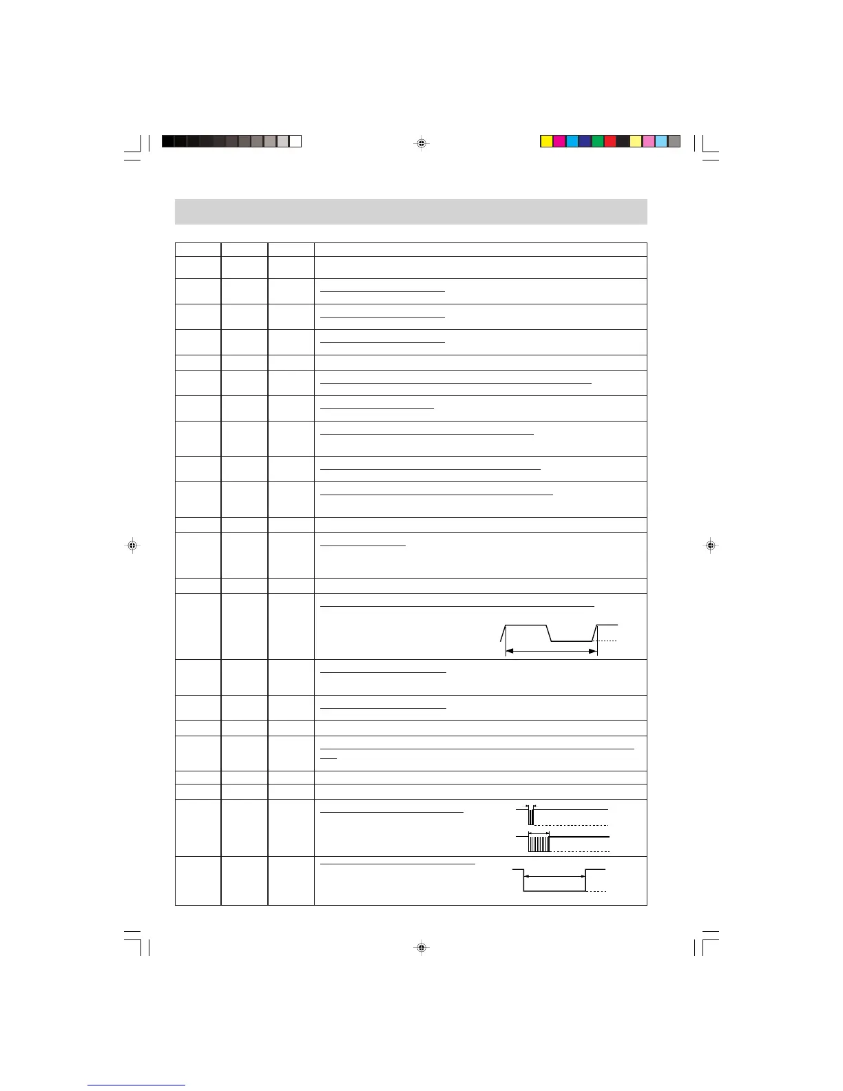
The I/O signal of the LSI(IXA089DR) are detailed in the following table.
A
B
0.1 sec.
2 sec.
H : +5V
L: 0V
H : +5V
L: 0V
(Grill or dual)
ON
OFF
During
cooking
L
GND
H.
20.0 msec
H : +5V
L : 0V
1-3 SEG21- OUT Terminal not used.
SEG23
4 COM1 OUT Common data signal: COM1.
Connected to LCD (Pin No. 1)
5 COM2 OUT
Common data signal: COM2.
Connected to LCD (Pin No. 2)
6 COM3 OUT Common data signal: COM3.
Connected to LCD (Pin No. 3)
7 COM4 OUT Terminal not used.
8 VLC IN
Signal synchronized with commercial power source frequency.
Signal similar to VSS.
9 VSS IN Power source voltage: 0V.
VSS voltage of power source circuit input.
10 XIN IN
Internal clock oscillation frequency setting input.
The internal clock frequency is set by inserting the ceramic filter oscillation
circuit with respect to XOUT terminal.
11 XOUT OUT Internal clock oscillation frequency control output.
Output to control oscillation input of XIN.
12-15 K00-K03 IN Terminal to change functions according to the Model.
DC voltage in accordance with the Model in operation is applied to set up its
function.
16 TEST IN Connected to VC.
17 RESET IN Auto clear terminal.
Signal is input to reset the LSI to the initial state when power is supplied.
Temporarily set to "L" level the moment power is supplied, at this time the LSI
is reset. Thereafter set at "H" level.
18 HOLD IN/OUT Connected to VDD.
19 INT2 IN Signal synchronized with commercial power source frequency.
This is the basic timing for time
processing of LSI.
20 R81 IN Signal coming from encoder.
When the encoder is turned, the contacts of encoder make pulse signals. And
pulse signals are input into R81.
21 INT1 IN Signal coming from encoder.
Signal similar to R81. Pulse signals are input into INT1.
22 R83 OUT Terminal not used.
23 R90 IN To input signal which communicates the door open/close information to
LSI.
Door open "L" level signal (0V). Door close "H" level (+5V)
24-25 R91-R92 OUT Terminal not used.
26 VDD IN Connected to GND.
27 R40 OUT Signal to sound buzzer (2.0 kHz).
A: tact switch touch sound.
B: Completion sound.
28 R41 OUT
Grill heating element driving signal.
To turn on and off the grill heating
element relay (RY2). "L" level during grill
cooking or dual cooking; "H" level
otherwise.
Pin No. Signal I/O Description
R64ST_S.MANUAL 12/8/01, 11:01 am22