R-64ST - 31
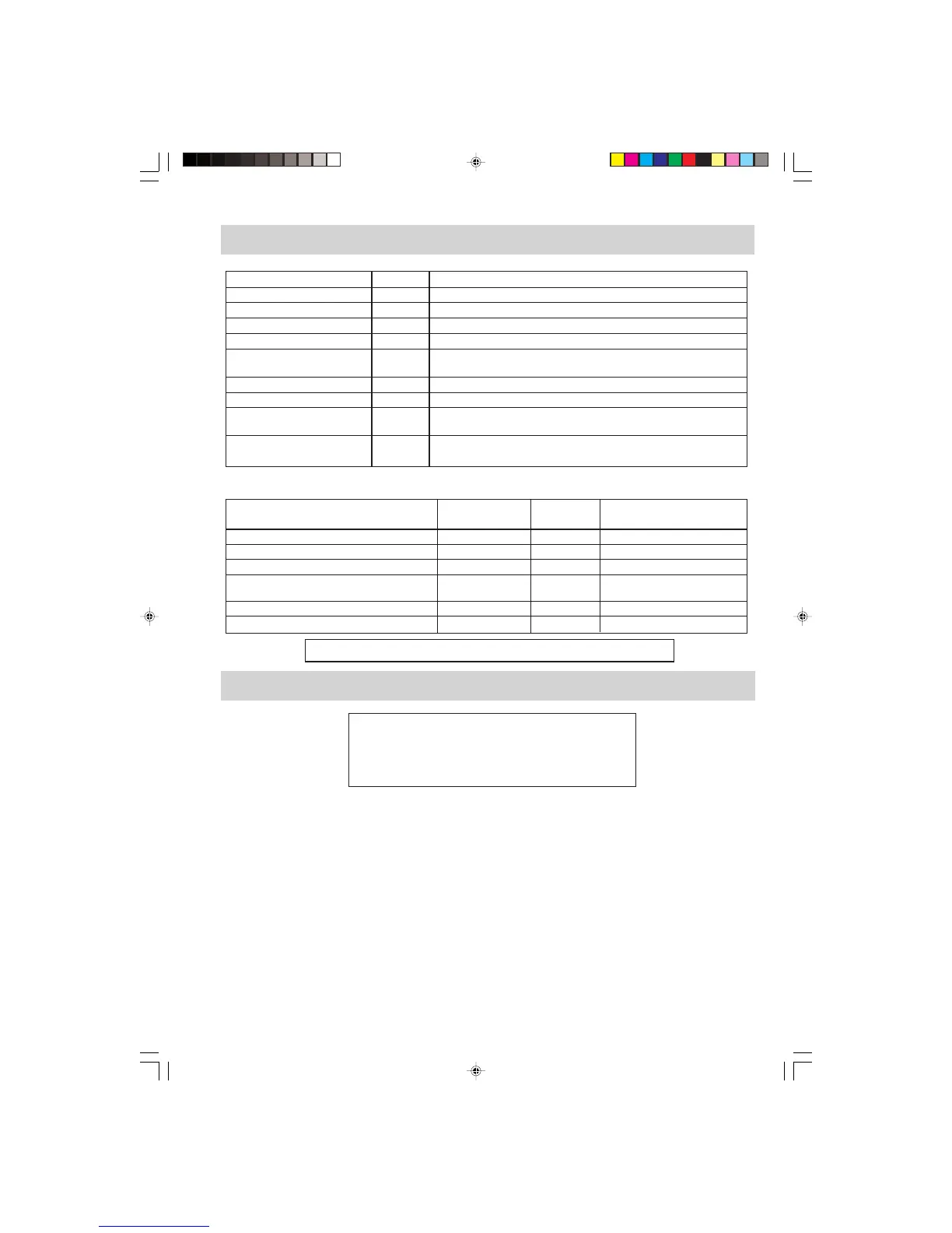
Parts Symbol Value / Data
Fuse F1 F8A
Fuse F2 20A
Thermostat (HVT.) TC1 150°C OFF 96°C ON
Thermostate (OVEN) TC2 150°C OFF 130°C ON
Grill heating element GH Approx. 27.9 Ω x 2 = 55.8Ω, 1.0 kW (500W x 2)
Insulation resistance > 10 MΩ
Oven lamp OL 240–250 V 25W
High voltage capacitor C AC 2100V 0.97µF
Magnetron MG Filament < 1Ω
Filament – chassis ∞ ohm.
Power transformer T Filament winding < 1Ω
Secondary winding Approx. 142 Ω / Primary winding Approx. 2 Ω
TEST POINTS ON CONTROL UNIT
Resistance (Disconnect the
In/Out put terminal Test Point Volt powerand door is closed)
Input terminal (Power supply) A1 - A3 230 V Approx. 1.04 kΩ
Input terminal (Stop switch) B1 - B2 - 0
Output terminal (Grill heating element) NO. of RY2 - A3 230 V Approx. 370 Ω
Output terminal
(Oven lamp, fan motor and turntable motor) A3 - A5 230 V Approx. 180 Ω
Output terminal (Earth) B2 - Chassis - 0
Output terminal (High voltage transformer) NO. of RY3 - A3 230V Approx. 370 Ω
WARNING: DISCONNECT THE PLUG WHEN MEASURING RESISTANCE.
TEST DATA AT A GLANCE
RE-WIRING
Ensure the following:
1. Wires must not touch:
a) High voltage parts.
(Magnetron, high voltage transformer, high voltage capacitor and high voltage rectifier assembly)
b) Parts that become hot.
(Heating elements, oven lamp, oven cavity magnetron and high voltage transformer)
c) Sharp edges.
(Bottom plates, oven cavity, waveguide flange, chassis support and other metallic parts)
d) Movable parts.
(Fan blade, any motor, switch, switch lever and open button)
2. Positive lock connectors are fitted correctly. Ensure the locking pin is located correctly.
3. Wires are connected correctly as per pictorial diagram.
4. No wire leads are trapped by the outer wrap.
WARNING: Before carrying out any work carry out 3D checks
1) Disconnect the supply.
2) Door opened, and wedged open.
3) Discharge high voltage capacitor.
WIRING / RE-WIRING
R64ST_S.MANUAL 12/8/01, 11:01 am31