R-9X55
WEIGHT SENSOR ASSEMBLY REMOVAL
1. CARRY OUT 3D CHECKS
sor assembly to the oven cavity.
2. Remove the turntable motor, referring to
“TURNTABLE MOTOR REMOVAL”.
5. Disconnect the connector from the weight sensor assem-
bly.
3. Remove the four (4) screws holding the weight sen-
sor assembly to the base plate.
6. Remove the turntable gear A from the weight sensor as-
sembly.
4. Remove the four (4) screws holding the weight sen-
7. Now. the weight sensor assembly is free.
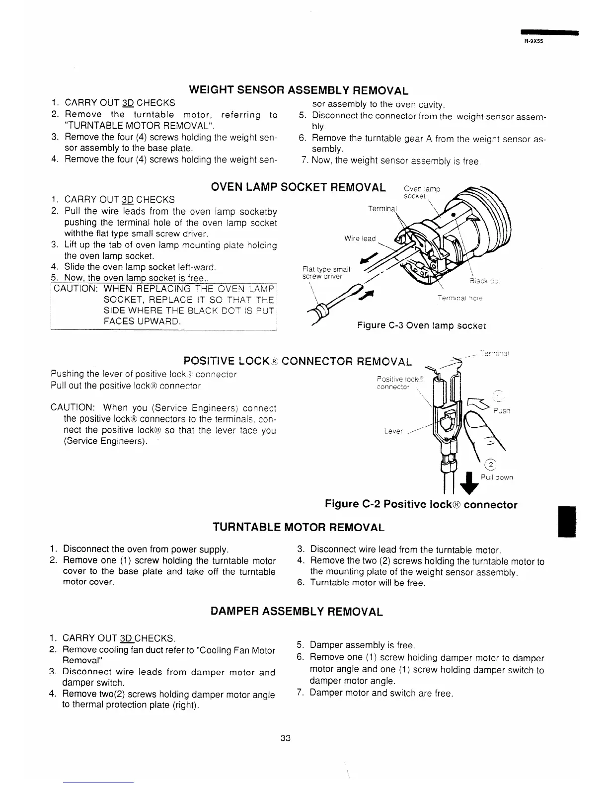
OVEN LAMP
so
1. CARRY OUT3JCHECKS
2. Pull the wire leads from the oven lamp socketby
pushing the terminal hole of the oven lamp socket
withthe flat type small screw driver.
3. Lift up the tab of oven lamp mounting piate hoiding
the oven lamp socket.
4. Slide the oven lamp socket left-ward.
5. Now, the oven lamp socket is free..
; CAUTION: WHEN REPLACING THE OVEN LAMP’
SOCKET, REPLACE IT SO THFtT THE
SIDE WHERE THE BLACK COT IS PiiT
FACES UPWARD.
CKET REMOVAL
screw oriver
ierm,:*a:
- _ i’” e
Figure C-3 Oven lamp socket
POSITIVE LOCK 3, CONNECTOR REMOVAL
Pushing the lever of positive lock c corxecrc:
Pull out the positive lock8 connector
PXltiVe iCCk 3
.xnnec:c-
CAUTION: When you (Service Engineers; connect
the positive lock3 connectors to the terminals. con-
nect the positive lock@ so that ihe lever face you
(Service Engineers). *
i-ever ,
Figure C-2 Positive lock@ connector
TURNTABLE MOTOR REMOVAL
1. Disconnect the oven from power supply.
2. Remove one (1) screw holding the turntable motor
cover to the base plate and take off the turntable
motor cover.
3. Disconnect wire lead from the turntable motor.
4. Remove the two (2) screws holding the turntable motor to
the mounting plate of the weight sensor assembly.
6. Turntable motor will be free.
DAMPER ASSEMBLY REMOVAL
1. CARRY OUT 3D-CHECKS.
2. Remove cooling fan duct refer to “Cooling Fan Motor
Removal”
3. Disconnect wire leads from damper motor and
damper switch.
4. Remove two(2) screws holding damper motor angle
to thermal protection plate (right).
5. Damper assembly is free.
6. Remove one (1) screw holding damper motor to damper
motor angle and one (1) screw holding damper switch to
damper motor angle.
7. Damper motor and switch are free.
33