COOLING FAN MOTOR WITH FAN THERMAL CUT-OUT REMOVAL
1.
CARRY OUT 3D CHECKS.
7. Remove cooling duct and fan motor ass’y from unit.
2. Disconnect wire leads from the cooling fan motor and fan
The cooling fan motor assembly is now free.
thermal cut-Oui.
8. Remove fan blade from fan motor shaft by pulling
3. Reiease the main harness from the hang and hole of the
fan retainer clip.
fan duct. And release.
9. Remove two (2) screws and nuts holding cooling fan
4. Release the snap band tab of the main harness from the
motor and fan thermal cut-out mounting plate. The
chassis support.
cooling fan motor is now free.
5. Remove three (3) screws holding the chassis support to
l&Remove the two (2) screws holding the fan thermal
rear cabinet, control panel back plate and wave guide.
cut-out to the mounting palte. Now the fan thermal
6. Release one (1) tab holding cooling fan duct to air guide.
cut-out is free.
CONVECTION MOTOR REMOVAL
I. CARRY OUT 3D CHECKS.
6. Remove two (2) screws holding the convection mo-
2. Release the door spring (!eft) from the door cam (left) and
tor mounting angle to the heater duct and base cabi-
the base plate.
net.
3. Remove one (1) screw holding the insulator to base plate.
7. Take out the convection motor assembly from the
4. Remove the insulator from the base plate.
unit. The convection motor assembly is now free.
5. Disconnect wire leads from the convection motor.
8. Remove two (2) screws and nuts holding the motor
Remove the convection fan belt and pulley(M).
to mounting angie.
9. Convection motor is now free.
HEATER UNIT ASSEMBLY REMOVAL (HEATING ELEMENT/THERMISTOR)
:
C4RRY OUT 3D CHECKS.
7 Remove convZtion motor ass’y refer to
-I
“Convection
idio!or Removal”.
‘;
-I
D3r:sxnnect wire leads from oven thermal cut-olu? and
teaier eremen!.
,
-- 5epi3L’e TWO !2j
screws hoidlng ine thermistor assembly
tr: 1w heater duct assembiy.
.3
tjis::onnec:
wire leads from thermlsior assembly. l\j,o)~4’.
‘- --~y-?-!isti;r ~:cq=lq$~V is free
.s It-..
VL.“S -
^
- =ie!easp tws
I_
121 snap bands
from the hoies holding wire
‘--3*:zss tc! the thermai protection p!ate (iefil.
- -
-.-3FjSife eie*iren :; 1) SCrewS !3
.,
screws from outsrde ana 8
i--‘F:j%,/~ i:or ir-jSf&
,/_b.
hoiding neater duct tc tne over- :a\,-
,..
2
_ VI
- ?r. n&~~er
-1 di-11; assemoly is now free.
? -
,::
-:er;=L’
e one il j nut and one (1; washer hoidrng the con-
:‘ectiori ian to the bearing assembly.
.eF r-
L’ *?yo1:s
convection fan from the bearing assembly.
: : .+nxve two (2) screws holding the bearing mounting
pie
to the heater duct assembly.
9 Remove three (3) screws holding the thermal protection fL
plate ileft; to the heater duct assembly.
: %.:Remove the thermal
prot
ection plate (left, and therma!
proiection sheet (left! from the heater duct assembiy.
14.Remove two (2) screws holding the convection
heater to the heater duct assembly.
15.Remove two (2) screws holding the two heater ele-
men?s holder to the heater duct assembly.
16. Remove two heater elements holders from the con-
veciion heaier.
? 7.Vow. the convection heater. is free.
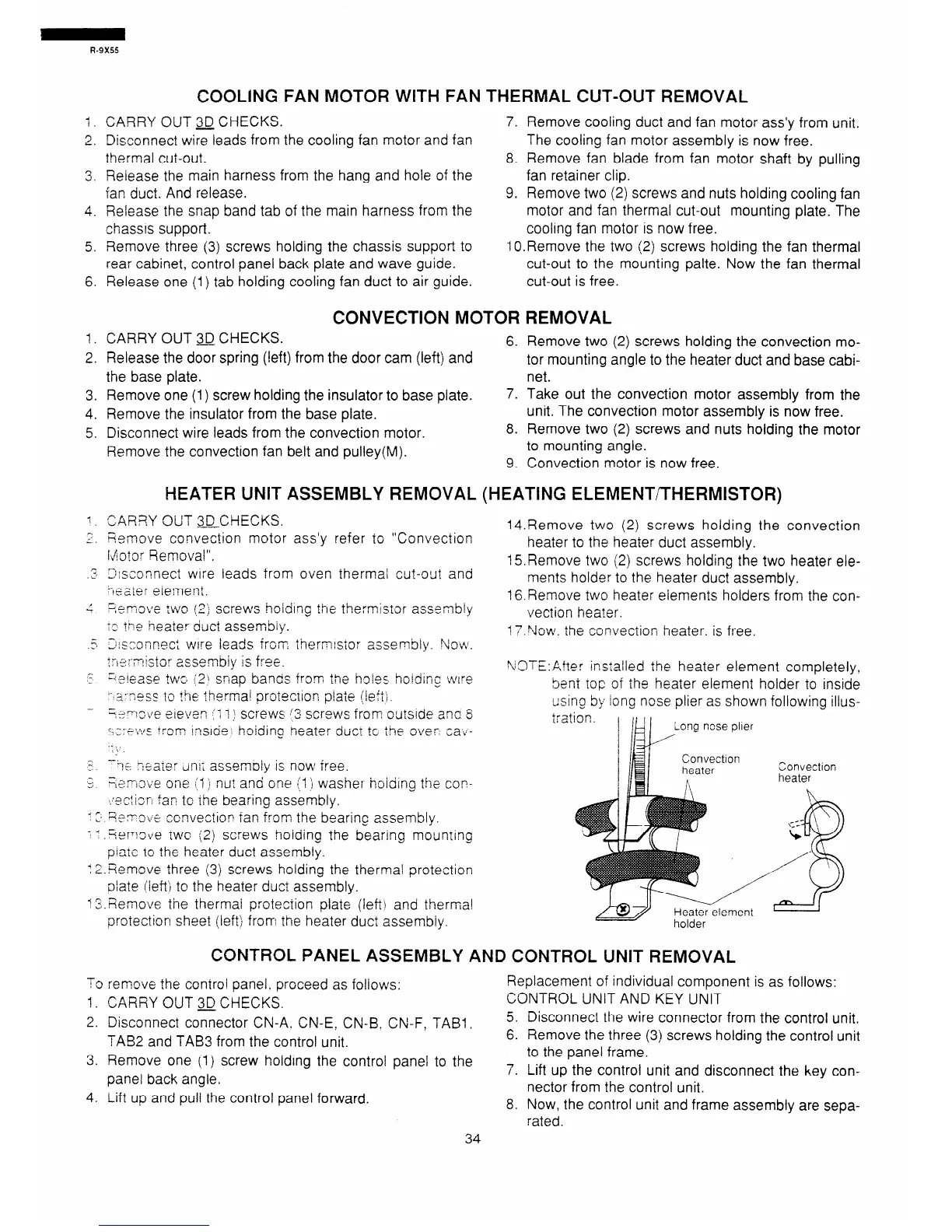
\OTE:Atter installed the heater element completely,
bent top of ihe heater element holder to inside
usino by iong nose plier as shown following illus-
Convection
heater
CONTROL PANEL ASSEMBLY AND CONTROL UNIT REMOVAL
To remove the control panel. proceed as follows:
Replacement of individual component is as follows:
1. CARRY OUT 3D CHECKS.
CONTROL UNIT AND KEY UNIT
-
2. Disconnect connector CN-A. CN-E, CN-B, CN-F, TAB1 t
-.
TAB2 and TAB3 from the control unit.
z.
3. Remove one (1) screw holding the control panel to the
panel back angle.
7
4. Lift up and pull the control panel forward.
8.
34
Disconnect the wire connector from the control unit.
Remove the three (3) screws holding the control unit
to the panel frame.
Lift up the control unit and disconnect the key con-
nector from the control unit.
Now, the control unit and frame assembly are sepa-
rated.
 Loading...