R-9X55
POWER SUPPLY CORD REPLACEMENT
Removal
1. CARRY OUT 3D CHECKS.
6. Pull out the power supply cord from the hole in the rear
cabinet.
2. Disconnect the brown wire lead of the power supply
cord from the fuse holder.
3. Cut away the connector CE-230.
4. Remove the single (1) screw holding the green/yel-
low wire lead to the base plate.
5. Remove the two (2) screws holding the cord anchor-
ages upper and lower to the base plate.
7. Now, the power supply cord is free.
Re-install
1. Insert the power supply cord into the hole of the rear cabi-
net.
2. Hold the power supply cord to the bottom plate by fixing
the cord anchorage upper and lower as follows.
r
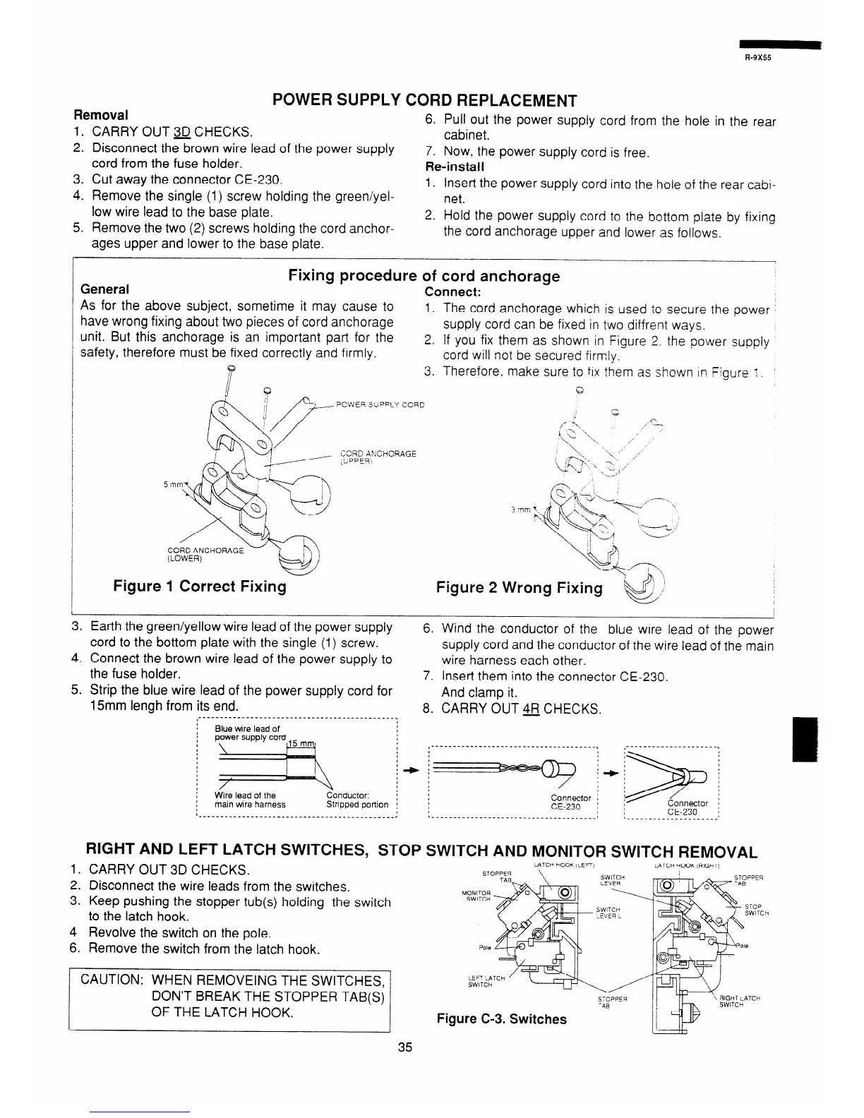
General
Fixing procedure of cord anchorage
Connect:
As for the above subject, sometime it may cause to
have wrong fixing about two pieces of cord anchorage
1. The cord anchorage which is used to secure the power
unit. But this anchorage is an important part for the
supply cord can be fixed in two diffrent ways.
safety, therefore must be fixed correctly and firmly.
2. If you fix them as shown in Figure 2. the power supply
cord will not be secured firmly.
9
i
3. Therefore. make sure to fix them as shown in Figure 1.
P CWEE SLIPPLY CORD
Figure 1 Correct Fixing
CORD ANCHORAGE
,UPPE9
Q
c
,--;%.
a-.
.A
i ~-2 x.,
,
‘\ ‘\.
\ - ‘, “
,7-J.
X‘
1,‘
:d!;
\ , s-;, ,’
Figure 2 Wrong Fixing
3. Earth the green/yellow wire lead of the power supply
cord to the bottom plate with the single (1) screw.
6. Wind the conductor of the blue wire lead of the power
supply cord and the conductor of the wire lead of the main
4. Connect the brown wire lead of the power supply to
wire harness each other.
the fuse holder.
7. Insert them into the connector CE-230.
5. Strip the blue wire lead of the power supply cord for
And clamp it.
15mm lengh from its end.
8. CARRY OUT $FJ CHECKS.
________________________________________------
Blue wire lead of
: Wire lead of the
Conductor:
: main wire harness Stnpped portron
+ +=-ayor 1 * @i&j
CE-230 :
.______________________________________I
L____.________________I
RIGHT AND LEFT LATCH SWITCHES, STOP SWITCH AND MONITOR SWITCH REMOVAL
1. CARRY OUT 3D CHECKS.
LATCH hCOK ,LEF’I
ulTCH ‘itOOK (RIGI-T)
2. Disconnect the wire leads from the switches.
3. Keep pushing the stopper tub(s) holding the switch
to the latch hook.
4 Revolve the switch on the pole.
6. Remove the switch from the latch hook.
CAUTION: WHEN REMOVEING THE SWITCHES,
DON’T BREAK THE STOPPER TAB(S)
OF THE LATCH HOOK.
Figure C-3. Switches
35