Do you have a question about the Sharp VL-AH30U and is the answer not in the manual?
Perform safety checks before returning the video camera recorder to the user.
Details of AC adapter and battery charger and battery pack specifications.
Information for US customers on obtaining service and accessories.
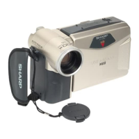
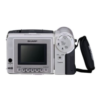
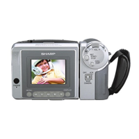
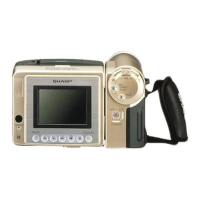
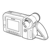
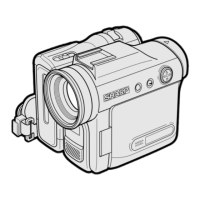
Labeling of external controls and features on different views of the camcorder.
Step-by-step guide for disassembling the camera section of the device.
Procedure for disassembling the VCR main body and its components.
Steps to remove the VCR lid, AV unit, and its cover.
Steps for disassembling LCD holder and removing cassette compartment lid.
Procedure for disassembling the LCD panel.
Precautions, removal, and mounting steps for replacing the CCD sensor.
List of necessary jigs, tools, and parts for mechanism adjustment and maintenance.
VCR mechanism inspection/maintenance list and important notes.
Procedures for checking reel disk height and playback torque.
Procedures for checking tension pole position and rewind torque.
Steps for preparing and adjusting tape travel system components like rollers.
Procedures for adjusting guide, checking waveforms, and tape travel.
Guidelines for mechanism assembly and explanation of different operating modes.
Procedures for disassembling cassette control ass'y and removing drum/base.
Instructions for installing drum assembly components and matching phase.
Steps for installing various mechanism components like gears and levers.
Procedure for initial setting of the E2PROM IC and its data.
Steps for adjusting Y/C, Audio, and LCD circuits.
Procedures for VCR section adjustment.
Procedure for setting up the VCR section adjustment mode.
Method for adjusting the battery shut-off voltage.
Detailed steps for adjusting the power circuit.
Procedures for checking various power supply voltages.
Procedures for checking DSP and LCD power supply voltages.
Method for adjusting the Y/C circuit.
Procedures for adjusting VCO, H-position, pulse, bias, and white balance.
Steps for adjusting the playback switching point in the system controller.
Necessary tools, instruments, and connection diagrams for camera servicing.
General steps for camera adjustment, including power, focus, and signal.
Procedures for adjusting sync level, iris AE, and black balance/AF noise.
Steps for adjusting white balance, color gain, and outdoor white balance.
Categorization of common problems and their potential causes.
Guides for troubleshooting camera section issues and charging mode problems.
Diagram illustrating the overall system architecture and component interactions.
Diagram showing the flow of the video signal through the device.
Diagram illustrating the head amplifier process and signal flow.
Diagram showing the power supply distribution across the system.
Block diagram of the main battery circuit and charging system.
Diagram showing the lens drive system and its components.
Overall schematic diagram showing major PWB interconnections.
Schematic diagram of the Analog-to-Digital Converter (ADC) circuit.
Schematic diagram of the Digital Signal Processor (DSP) circuit.
Schematic diagram of the audio circuit.
Schematic diagram of the System Controller (SYSCON) circuit.
Schematic diagram for the internal LCD interface.
Schematic diagram for the LCD controller circuit.
Schematic diagram of the power supply circuits.
Schematic diagram for the Input/Output (I/O) circuits.
Schematic diagram of the System DAC circuit.
Schematic diagram of the battery charging circuit.
Schematic diagram for the RF section of the VL-A10U model.
Schematic diagram for the RF section of the VL-AH30U model.
Schematic diagram of the Timing Generator (TG) circuit.
Schematic diagram of the CDS (Correlated Double Sampling) circuit.
Schematic diagram of the Lens Drive (LDRV) circuit.
Schematic diagram of the Head Amplifier circuit.
Schematic diagram of the Motor Driver circuit.
Schematic diagram of the CCD Sensor circuit.
List of replacement electrical components including ICs, transistors, and transformers.
List of PWB assemblies, noted as not being replacement items.
List of diodes, packaged circuits, capacitors, and resistors for replacement.
List of replacement parts for mechanism, cabinet, and camera sections.
List of accessories supplied with the product, not for replacement.
Exploded view of the cassette housing control unit.
Exploded view illustrating the assembly of the camera unit.