43
VL-AX1U
Item
Adjustment method
(1) White balance adjustment is performed repeatedly.
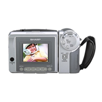
(7)White balance adjustment
• Measurement terminal:
EE output
• Address:
"0128" INDOOR_W/B R
"012A" INDOOR_W/B R
• Measuring instrument:
Vector scope
• Object:
Grey scale
• Data variation width:
"0000" to "03FF"
(8) Indoor white gain adjustment
• Measurement terminal:–
• Address: 0001
• Measuring instrument:–
• Object: White pattern
• Data variation width:–
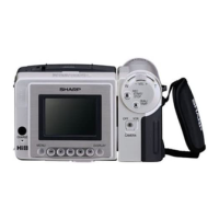
(1) Color gain adjustment is performed repeatedly.
Adjustment address
Red amplitude 1.85 ± 0.05 time (burst ratio) : "013A"
Blue amplitude 1.50 ± 0.05 time (burst ratio) : "013C"
Yellow amplitude 1.35 ± 0.05 time (burst ratio) : "07DE"
Red phase 103° ± 1° : "0138"
Blue phase 358° ± 2° : "0136"
Yellow phase 164° ± 2° : "07DD"
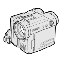
(10) Auto white balance adjustment
• Measurement terminal:
EE output
• Address:
"000C" OUTDOOR R
"000E" OURDOOR B
• Measuring instrument:
Vector scope
• Object:
Grey scale
• Data variation width:
"0000" to "03FF"
(1) The color temperature conversion filter (LB165) is mounted in front of lens.
(2) Indication of vector scope is observed in the grey scale standard record state, and
an adjustment is made so that the luminous dots are located in the following
positions:
R-Y 0 ± 5% (burst ratio)
B-Y 0 ± 5% (burst ratio)
(11) Outdoor white gain adjustment
• Measurement terminal:–
• Address: 0001
• Measuring instrument:–
• Object: White pattern
• Data variation width:–
(9)Color gain adjustment
• Measurement terminal:
EE output
• Address:
"013A" CGIN RYG
"013C" CGIN BYG
"0138" CMAT RYG
"0136" CMAT BYG
"07DE" Yellow
amplitude
"07DD" Yellow phase
• Measuring instrument:
Vector scope
• Object:
Waveform monitor color bar chart
• Data variation width:
"0000" to "00FF"
(1)The adjustment is automatically done by writing the data "05" at the address "001" in
the signal system adjustment mode.
When the adjustment is normally completed, the data "FF" will be return to the address
"001". If another data except "FF" is returned, it will be judged as the poor adjustment.
(1) Attach the color temperature conversion filter (LB165) in front of the lens.
(2) The adjustment is automatically done by writing the data "06" at the address "001"
in the signal system adjustment mode.
When the adjustment is normally completed, the data "FF" will be return to the
address "001". If another data except "FF" is returned, it will be judged as the poor
adjustment.