VL-E630S/VL-E630H
VL-E680S/VL-E97E
VL-E99E
VL-E630S/VL-E630H
VL-E680S/VL-E97E
VL-E99E
3
4. MECHANISM ADJUSTMENT
4-3. Mechanism checks and adjustments
4-3-4. Checking and adjusting the tension pole position
(1) Check
When winding of P5-120 tape is started, check whether the tension pole is in the specified position against Si roller
as shown or not.
If it is not in the specified position, remove the cassette and adjust the position in the following procedure.
5. ADJUSTMENT OF VCR
5-1. ADJUSTMENT OF VCR SECTION
5-1-5. Y/C circuit adjustment method
Measuring point LCD panel display surface
Address 11, 12
Mode VCR AV input
Adjusting method Set the data of address 11 and 12.
Adjustment standard
11=BD
12=8E
Remarks ———————
5-1-7. Adjustment of LCD display circuit
10. Inverter input voltage setting
5-2. ADJUSTMENT OF CAMERA SECTION
5-2-2. Adjustment procedures
5-2-2-2. Auto focus adjustment
• Basic iris adjustment
1) Set up the auto focus adjustment mode. (Write 01 to the address 1FE)
2) Write the adjustment data 09, 0A and 0B one after the other to the address 1FF, the adjustment are as follows.
5-2-2-3.
Before starting these adjustments, set up the auto focus adjustment mode.
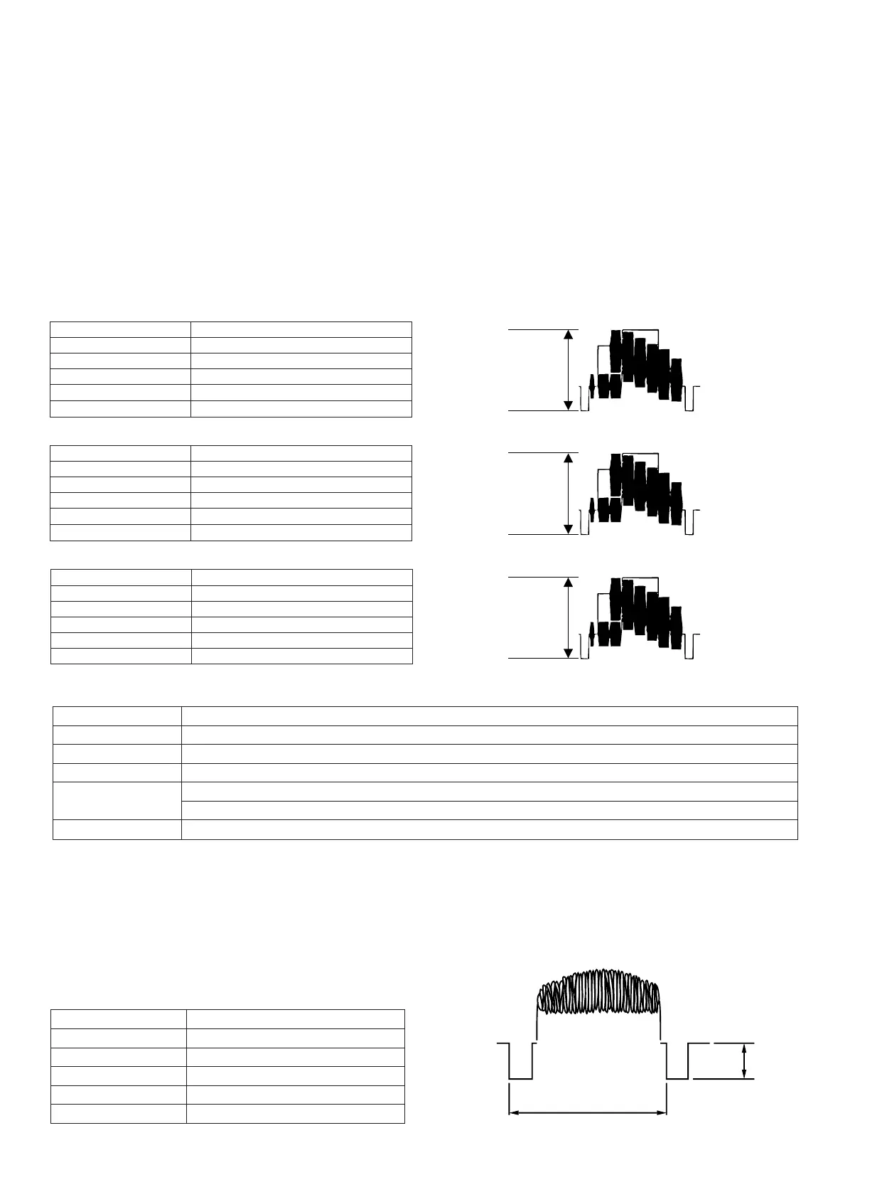
• Sync level adjustment
Measuring instrument
Oscilloscope
Subject Anything
Tape —
Test point
VIDEO OUT (Terminated in 75Ω)
Adjustment address 1F8
Adjustment level 300mVp-p
1H
Video
SYNC
300mVp-p
2. Adjustment of input Y level
Measuring instrument Oscilloscope
Mode VCR STOP
Input signal Color bar
Measuring point TL801
Adjustment address 32
Adjustment level 500 mVp-p ± 20 mVp-p
3. Adjustment of playback Y level
Measuring instrument Oscilloscope
Mode PB
Playback signal Color bar (JiGWR5-5CSP)
Measuring point TL801
Adjustment address 27
Adjustment level 500 mVp-p ± 20 mVp-p
5. Adjustment of Y-FM deviation
Measuring instrument
Oscilloscope
Mode REC/PB (self-playback/recording)
Input signal Color bar
Measuring point TL801
Adjustment address 34
Adjustment level 500 mVp-p ± 20 mVp-p