5-15
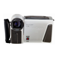
VL-H870U
VL-H875U
VL-H890U
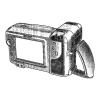
VL-H860S/H/VL-H870S
VL-H890S/VL-H94E
VL-H96E/VL-H960E
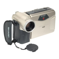
VL-H860S/H/VL-H870S
VL-H890S/VL-H94E
VL-H96E/VL-H960E
When you have finished, write FF to the adress 1FE to exit camera signal
adjustment mode.
Measuring instrument Vector scope
Subject Gray scale
Tape —
Test point VIDEO OUT (Terminated in 75 Ω)
Adjustment address R-OUT DOOR 016
B-OUT DOOR 018
Adjustment level R-OUT DOOR; 0 ± 3 %
B-OUT DOOR; 0 ± 3 %
1) Attach the color temperature conversion filter (JiGHOYA-LB165) to the front of the lens.
2) Using the addresses R-OUT DOOR 016 and B-OUT DOOR 018, adjust the spot to the center.
3) Take off the color temperature conversion filter.
8. Out door white balance adjustment
7. Color gain adjustment
B spot
R-Y
B-Y
R spot
R level
107°
340°
Burst
B level
Measuring instrument Vector scope
Subject Color bar chart
Tape —
Test point VIDEO OUT (Terminated in 75 Ω)
Adjustment address R GAIN 0DD
B GAIN 0DB
R MAT 0D7
B MAT 0D9
Adjustment level R GAIN; Burst ratio 1.2 ± 0.1
B GAIN; Burst ratio 1.0 ± 0.1
R MAT; 107 ± 2°
B MAT; 340 ± 2°
1) Using the address 0DD, adjust the R level to a burst ratio of 1.2.
With the address 0DB, adjust the B level to a burst ratio of 1.0.
2) Using the address 0D7, adjust the R phase to 107°. With the
address 0D9, adjust the B phase to 340°.
3) Repeat the above steps 1) and 2).
Measuring instrument Vector scope
Subject Gray scale
Tape —
Test point VIDEO OUT (Terminated in 75 Ω)
Adjustment address R-W/B 010, B-W/B 012
Adjustment level R-W/B 0 % ± 3 %
(E, EW, EX model) B-W/B 0 % ± 3 %
(S, H model) R-W/B 19 % ± 3 %
B-W/B -11 % ± 3 %
6. White balance adjustment
1) E, EW, EX model adjust the spot to the center of vector scope (R-
Y : 0%, B-Y : 0%) using address 010 and 012.
S, H model adjust the spot to the point of vector scope (R-Y : 19%,
B-Y : -11% ratio to burst) using address 010 and 012.
Spot
R-Y
B-Y
Center point
Spot
R-Y
B-Y
[S, H] [E, EW, EX]
5. Burst gain adjustment
Measuring instrument Oscilloscope
Subject None
Tape —
Test point VIDEO OUT (Terminated in 75 Ω)
Adjustment address 1F9
Adjustment level 300mVp-p
1) Measure the burst signal level on the oscilloscope. Using the
address 1F9, adjust the burst amplitude to 300mVp-p.
4. Data processing after adjusting the black balance
1) 5 digit subtraction from ROB adjustment data at AGC MIN (address 19Ch) = (address 19ch) - 5h
5 digit subtraction from ROB adjustment data at AGC MAX (address 19Dh) = (address 19Dh) - 5h
5 digit subtraction from ROB adjustment data at GAIN UP (address 19Eh) = (address 19Eh) - 5h