VL-H870U
VL-H875U
VL-H890U
VL-H870U
VL-H875U
VL-H890U
4-2
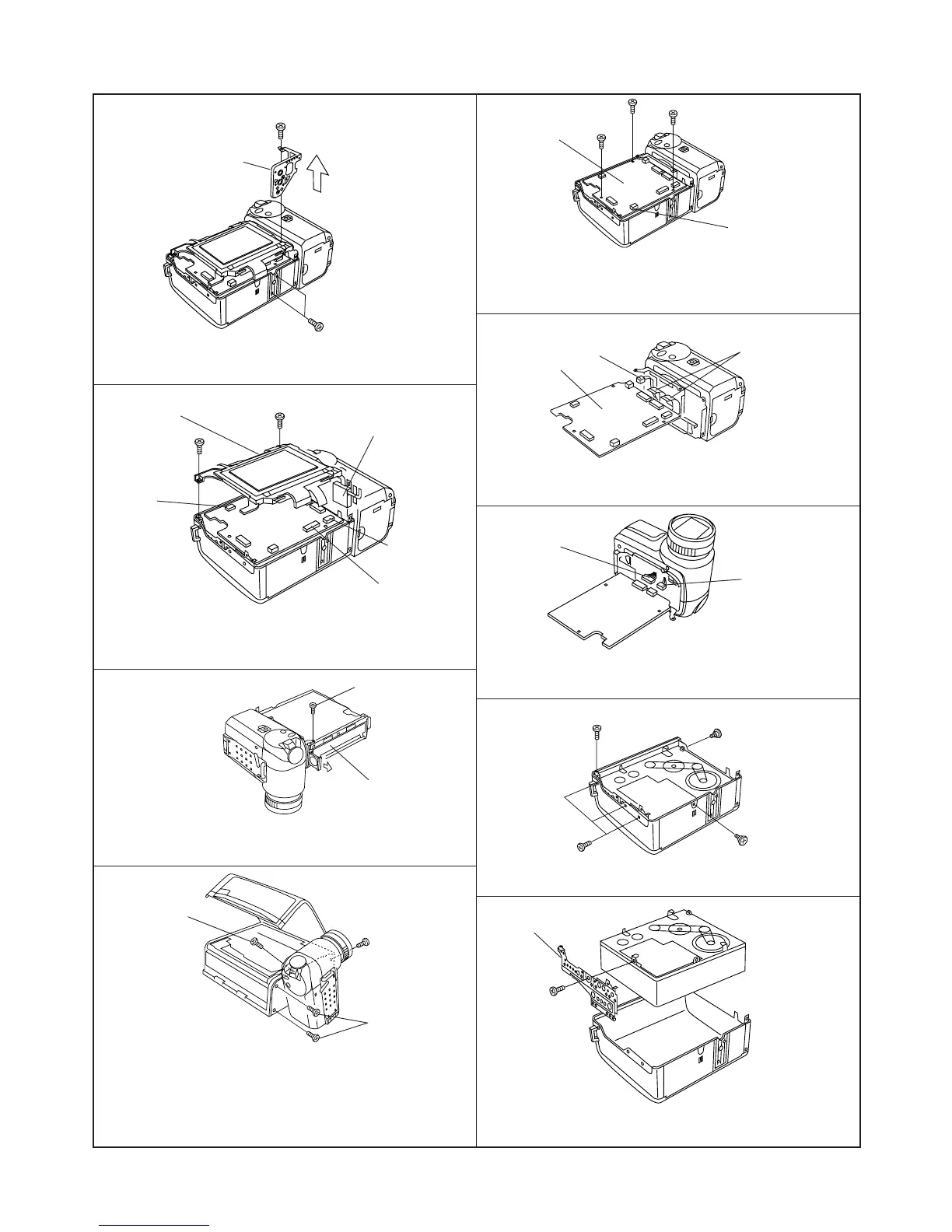
<2. Remove the Tripod Angle.>
(d)
(d)
(1) Remove the screws(d)XiPSF20P04000(3pcs.), pull the Tri-
pod Angle.
Tripod Angle
<3. Removal of the LCD unit>
(1) Remove the FPCs from connectors A,B and C.
(2) Remove the screws(d)XiPSF20P04000(1pc.) and (b)LX-
HZ0018TAFF(1pc.).
(b)
LCD unit
(d)
Inverter transformer
B
A
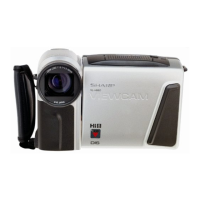
<4. Removal of the V.Cabinet>
(2) Turn the Camera section to right angle, remove theTilt side
fixing screws (g)LX-HZ0045TAFF (2pcs.), the bottom side
screw (b)LX-HZ0018TAFF(1pc.), open the VCR lid, and
remove the slant wise screw (d)XiPSF20P04000 (1pc.).
Note:
The Tilt section is setting with the parts of the Camera section .
(Never remove the parts of Camera section only.)
(1) • Firstly, remove the Lithium Holder.
• Turn to upside the surface of V.lid, remove the
V.Cabinet fixing screw (b)LX-HZ0018TAFF (1pc.).
Remove the Lithium
Holder
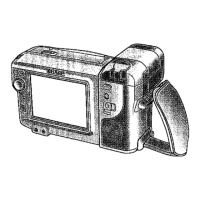
(f)
Microphon connector
(f)
Main P.W.B
(f)
(3) Remove the Microphon connector.
Remove the main P.W.B.fixing screws (f)XiPSD20P03000(3pcs.).
Lift the main P.W.B. in the arrow direction and remove the
connection "B to B".
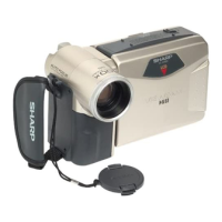
<5. Removal of the main P.W.B>
Main P.W.B
Camera FPC
Lithium connector
(1) Remove the Camera FPCs(2pcs.) are connected with main
P.W.B. and the Camera section, and remove the Lithium
connector.
Remove the battery
connector
Remove EJECT TURN
S.W. connector
(2) The same as process4., remove the battery connector in the
reverse side of P.W.B. and EJECT TURN S.W. connector,
and disconnect the Tilt section and main P.W.B..
<6. Removal of the Cabinet and Mechanism>
(b)
(e)
(e)
(d)
(1) Remove the screws (b)LX-HZ0018TAFF (1pc.), (d)
XiPSF20P04000 (3pcs.) and (e) LX-BZ0191TAFD (2pcs.).
(2) Pull the Mechanism from K.S.V.Cabinet, remove the
screw(e)LX-BZ0191TAFD(1pc.) and the side angle.
(e)
Side angle
C
(b)
V Cabinet
(d)
(b)
(g)