L-PDl U
2) In Fig. 2 fit the screws @
Tightening torque 40 + 4mN.m (0.4 + 0.04kgcm)
3) In Fig. 3 fit the screw @.
Tightening torque 40 f.4mN.m (0.4 + 0.04kgcm)
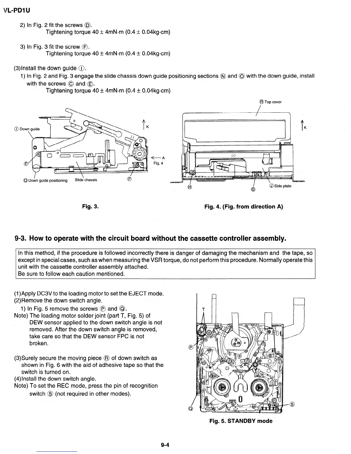
(3)lnstall the down guide @.
1) In Fig. 2 and Fig. 3 engage the slide chassis down guide positioning sections @ and 0 with the down guide, install
with the screws 0 and 0.
Tightening torque 40 + 4mN-m (0.4 & 0.04kgcm)
@ Top cover
I
0 Down guide positioning
Slide‘ chassis
Fig. 3.
9-3. How to operate with the circuit board
without the cassette controller assembly.
+A
Fig. 4
Fig. 4. (Fig. from direction A)
In this method, if the procedure is followed incorrectly there is danger of damaging the mechanism and the tape, so
except in special cases, such as when measuring the VSR torque, do not perform this procedure. Normally operate this
unit with the cassette controller assembly attached.
Be sure to follow each caution mentioned.
(1)Apply DC3V to the loading motor to set the EJECT mode.
(2)Remove the down switch angle.
1) In Fig. 5 remove the screws @ and @I.
Note) The loading motor solder joint (part T, Fig. 5) of
DEW sensor applied to the down switch angle is not
removed. After the down switch angle is removed,
take care so that the DEW sensor FPC is not
broken.
(3)Surely secure the moving piece @ of down switch as
shown in Fig. 6 with the aid of adhesive tape so that the
switch is turned on.
(4)lnstall the down switch angle.
Note) To set the REC mode, press the pin of recognition
switch @ (not required in other modes).
Fig. 5. STANDBY mode