VL-PDl U
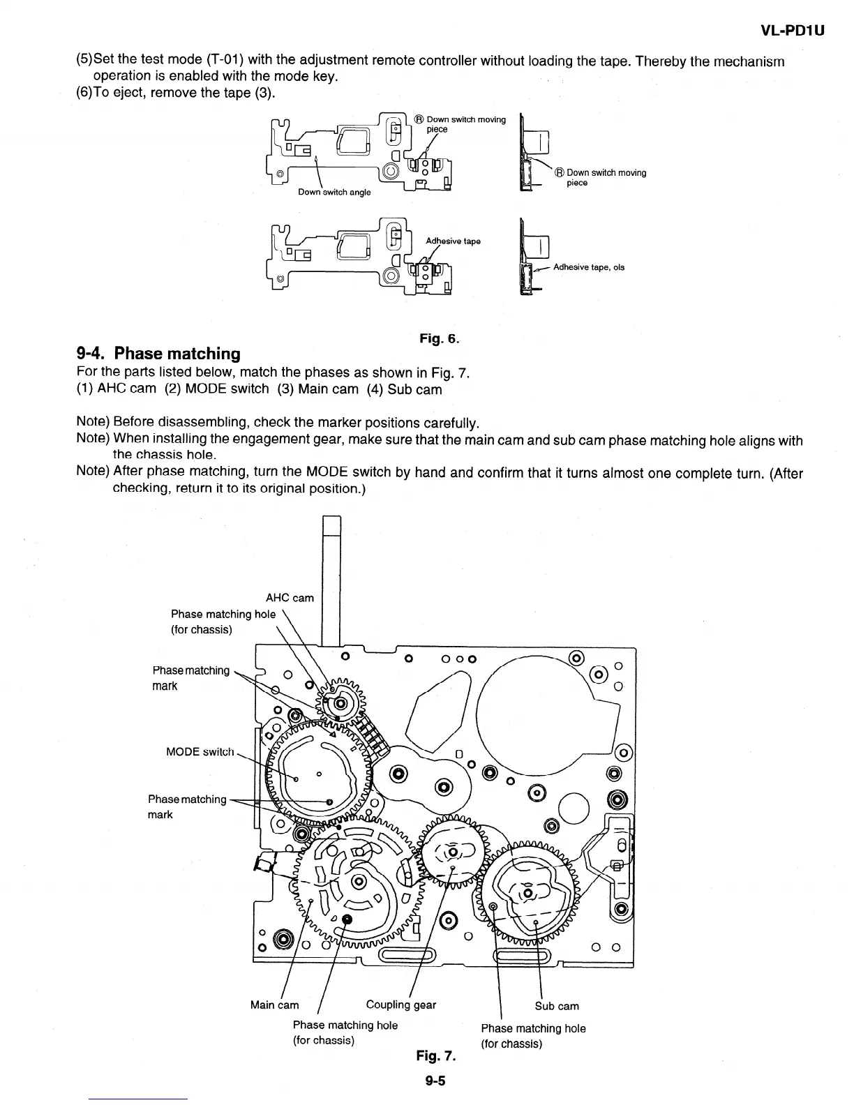
(5)Set the test mode (T-01) with the adjustment remote controller without loading the tape. Thereby the mechanism
operation is enabled with the mode key.
(6)To eject, remove the tape (3).
moving
tape
@ Down switch moving
piece
Adhesive tape, ok
9-4. Phase matching
Fig. 6.
For the parts listed below, match the phases as shown in Fig. 7.
(1) AHC cam (2) MODE switch (3) Main cam (4) Sub cam
Note) Before disassembling, check the marker positions carefully.
Note) When installing the engagement gear, make sure that the main cam and sub cam phase matching hole aligns with
the chassis hole.
Note) After phase matching, turn the MODE switch by hand and confirm that it turns almost one complete turn. (After
checking, return it to its original position.)
AHC cam
Phase matching hole \
(for chassis)
Phase matching
mark
MODE switch
Phase matching
mark
Main dam
/
Coupling gear
Phase matching hole
(for chassis)
Fig. 7.
I
Sub cam
Phase matching hole
(for chassis)
9-S