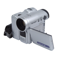
VL-PD3U
SHARP
SERVICE MANUAL
LIQUID CRYSTAL
DIGITAL CAMCORDER
NTSC
MODEL VL-PD3U
In
the interests
of user-safety (Required
by
safety regula-
tions
in some countries) the set should be restored to its
original
condition
and only
parts identical to
those
specified
be used.
CONTENTS
1
.
2 .
3
4:
5.
6
.
7.
0
.
9 .
Page
IMPORTANT SERVICE NOTES
......................................................................................................
l-l
SPECIFICATIONS
...........................................................................................................................
2-1
PART NAMES
..................................................................................................................................
3-1
DISASSEMBLY OF THE SET
.........................................................................................................
4-l
MECHANISM ADJUSTMENT JIGS AND PARTS
...........................................................................
5-l
INSPECTION AND MAINTENANCE
ITEMS AND
INTERVALS
................................................................................................................
6-1
MECHANICAL
ADJUSTMENTS AND
CHECKS
.............................................................................
7-l
TAPE RUNNING
ADJUSTMENT
.....................................................................................................
8-1
MECHANICAL SECTION
ASSEMBLY AND PARTS REPLACEMENT
(DISASSEMBLY
AND REASSENBLY)
...........................................................................................
9-l
1 O.ADJUSTlNG THE ELECTRICAL CIRCUITS
.................................................................................
10-l
11 .USEFUL TIPS
................................................................................................................................
11-l
12.SIGNAL FLOW DIAGRAMS
..........................................................................................................
12-1
13.BLOCK DIAGRAMS
......................................................................................................................
13-1
14.SCHEMATIC DIAGRAMS
..............................................................................................................
14-1
15SEMICONDUCTOR LEAD IDENTIFICATION
...............................................................................
15-l
16.PRINTED WIRING BOARD ASSEMBLIES
...................................................................................
16-1
17.REPLACEMENT PARTS LIST
.......................................................................................................
17-1
18.PACKING OF THE SET
.................................................................................................................
18-1
SHARP CORPORA,‘~ON
This document has been published to be used for
after sales service only.
The contents are subject to change without notice.