VL-PD3U
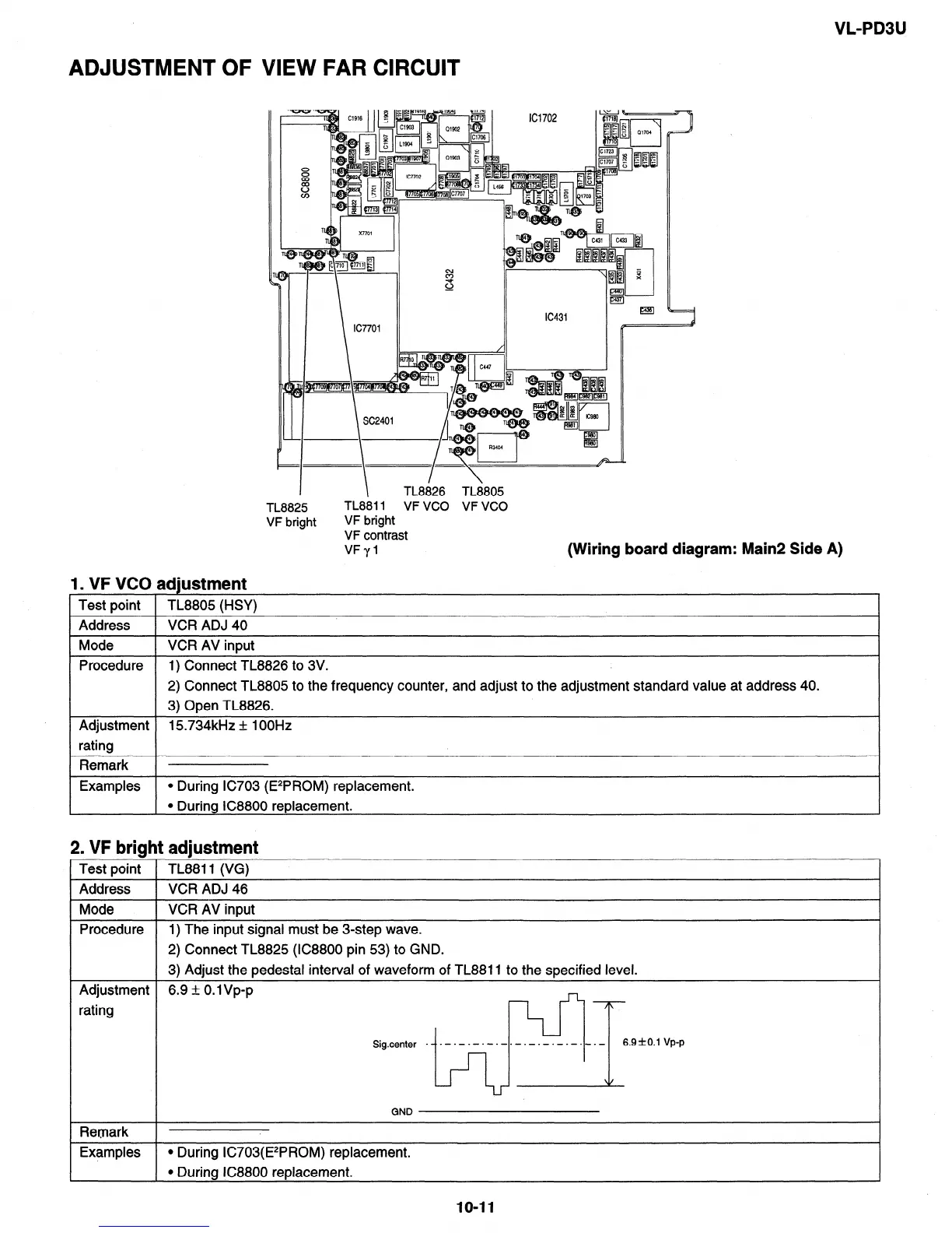
ADJUSTMENT OF VIEW FAR CIRCUIT
I
TL8825
VF bright
I
TL8826 TL8805
TL8811 VF VCO VF vco
VF bright
VF contrast
VFyl
(Wiring board diagram: Main2 Side A)
1. VF VCO adjustment
Test point
Address
TL8805 (HSY)
VCR ADJ 40
1 Mode 1 VCR AV input
Procedure
I I
1) Connect TL8826 to 3V.
2) Connect TL8805 to the frequency counter, and adjust to the adjustment standard value at address 40.
3) Open TL8826.
Adjustment 15734kHz + 1 OOHz
rating
1 Remark 1
Examples l During IC703 (E2PROM) replacement.
l Durina IC8800 replacement.
2, VF bright adjustment
Test point TL8811 (VG)
Address VCR ADJ 46
Mode VCR AV input
Procedure 1) The input signal must be 3-step wave.
2) Connect TL8825 (lC8800 pin 53) to GND.
3) Adjust the pedestal interval of waveform of TL8811 to the specified level.
Adjustment 6.9 I?I 0.1 Vp-p
rating
Sig_center . .~.-.~.~.~.-.-.-.-.~.-.-
*
6.9fO. 1 Vp-p
Remark
Examples
GND
l During IC703(E2PROM) replacement.
l During IC8800 replacement.
1041