VL-PD3U
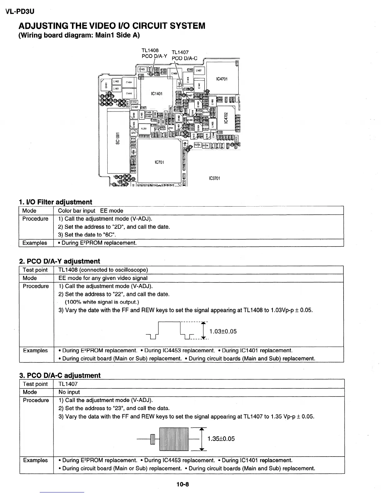
ADJUSTING THE VIDEO II0 CIRCUIT SYSTEM
(Wiring board diagram: Main1 Side A)
1. l/O Filter adjustment
Mode 1 Color bar input EE mode
Procedure 1) Call the adjustment mode (V-ADJ).
2) Set the address to “20”, and call the date.
3) Set the date to “6C”.
Examples 1
l During E*P.ROM replacement.
I
2. PC0 D/A-Y adjustment
Test point
Mode
Procedure
Examples
TLI 408 (connected to oscilloscope)
EE mode for any given video signal
1) Call the adjustment mode (V-ADJ).
2) Set the address to “22”, and call the date.
(100% white signal is output.)
3) Vary the date with the FF and REW keys to set the signal appearing at TL1408 to l.O3Vp-p + 0.05.
_____-_____
l-J
1.03+-0.05
_--__ a-
l During E*PROM replacement. l During lC4453 replacement. l During ICI401 replacement.
l During circuit board (Main or Sub) replacement. l During circuit boards (Main and Sub) replacement.
3. PC0 D/A-C adiustment
1 Test point 1 TL1407
1 Mode
1 No input
Procedure
1)
2)
3)
Call the adjustment mode (V-ADJ).
Set the address to “23”, and call the data.
Vary the data with the FF and REW keys to set the signal appearing at TL1407 to 1.35 Vp-p +, 0.05.
Examples l During E*PROM replacement. l During 164453 replacement. l During ICI401 replacement.
l During circuit board (Main or Sub) replacement. l During circuit boards (Main and Sub) replacement.
1 O-8