VL-PD3U
ADJUSTING THE LCD CIRCUIT
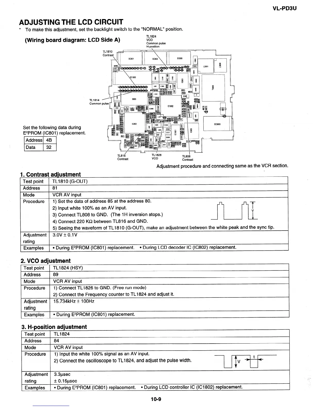
* To make this adjustment, set the backlight switch to the “NORMAL” position.
(Wiring board diagram: LCD Side A)
TL1824
vco
Common pulse
H-position
Set the following data during
E2PROM (IC801) replacement.
Address 4B
Data 32
TL1810
Contrast
JYFJT’
L5801
-/-/
TL816
TL1826
vco
Contrast
,r
I
TL808
Contrast
Adjustment procedure and connecting same as the VCR section.
1. Contrast adjustment
1 Test point 1 TL1810 (G-OUT)
1 Address 1 81
Mode VCR AV input
Procedure 1) Set the data of address 85 at the address 80.
2) Input white 100% as an AV input.
3) Connect TL808 to GND. (The 1 H inversion stops.)
4) Connect 220 K&2 between TL816 and GND.
2
5) Seeing the waveform of TL1810 (G-OUT), make an adjustment between the white peak and the sync tip.
Adjustment 3.ov + O.lV
rating
Examples 1 l During E2PROM (IC801) replacement. l During LCD decoder IC (IC802) replacement.
2. VCO adjustment
Test point TL1824 (HSY)
Address 89
Mode
VCR AV input
Procedure
1) Connect TL1826 to GND. (Free run mode)
2) Connect the Frequency counter to TL1824 and adjust it.
Adjustment
15734kHz + 1 OOHz
rating
Examples l During E2PROM (IC801) replacement.
3. H-position adjustment
Test point TL1824
1 Address 1 84
I
Mode VCR AV input
Procedure 1) Input the white 100% signal as an AV input.
t
2) Connect the oscilloscope to TL1824, and adjust the pulse width.
v-) +
Adjustment 3.3psec
% -
rating * 0.15psec
’ I
Examples l During E2PROM (IC801) replacement.
l During LCD controller IC (IC1802) replacement.
1 o-9