VL-PD3U
6.
INSPECTION
AND
MAINTENANCE
ITEMS AND
INTERVALS
In order
to keep the mechanical
section
always
in good condition,
perform the following inspection and
maintenance at regular intervals.
In
addition, after repair,
perform the
following maintenance items regardless of how long
the user
has
been
using
the
unit.
6-l. List of inspection and maintenance items
0
l l
l
Replace.
0
l
l
l
Clean.
/\e
l
l
Lubricate. * l
l l
Check.
Inspection
and
Time
of
use
(h)
Symptoms that
indicate Remarks
maintenance
location
500
1,000
1,500 2,000 3,000
need for maintenance
E
Tape
running
section
(see section 8-3) 0
E
0
0
q 0
l
Block-type noise
Note:
.
Drum section, Video
head
%’
(see section 8-3)
Cl
III
El
Cl
III 1 y$Yi$a:zgg’ng
Replace
the drum
ass’y if the
video head
is
cleaned
but
the
?
<Rollers>
envelope
is
not
still appeared.
.-
E
*
Replace
if
there
is
anything abnormal in the
rotation,
or if
there
is
run-out
2
(that
becomes
large).
(When
the
envelope is
normal,
refer to
“Il. USEFUL
TIPS”.)
Q,
<Other than the
above>
2
l
Clean
the
section
that contacts
the tape (especially the
lower
drum helical
l- section).
Use the specified
cleaning liquid.
Timing belt
- *o
-
*
0
*
0
l
The
tape
fails
to run.
l
Replace if there
is
anything
Pinch
roller
,,
,,
,., ,,.
,,
:
;;c~~p~enco;~s slack.
abnormal.
Capstan
motor
0
0 0
l
Abnormal noise
Swing arm
S reel base, Tu
reel base
-
*o
- *o *o
E
Center
pulley
shaft
A - A A *Abnormal noise
a,
=5
Intermediate pulley shaft
l
Lubricate
with
oil.
Swing arm
boss
[C
II
i
z?
B
Intermediate gear
A shaft,
Cosmo Hydro HV22
. . .
. Excepting intermediate
‘=
Intermediate gear
B
shaft
n
gear A and B
Tension-arm
shaft
A - A A
l
Tape damage
Cosmo Hydro HVIOO
. Abnormal
played-back
. . . .
Intermediate gear A and B
image
Note: Apply oil to the shaft, then
wipe
lightly with
a
cloth.
Loading motor
- *o -
* 0 * 0
l
Cannot eject.
l
Replace if anything
is abnormal
Mode switch
l
Fails to enter a mode.
(including
the
noise).
2
Abnormal
noise
* * *
*
*
l
The tape fails to run.
l
Replace any part that fails to
$
l
The tape becomes slack.
c
PB
.
VS/REW winding torque - * - * *
perform
within
the standard.
0
l
Tape damage
?!
2
PB . VS/R
l
loading back tension - *
-
* *
l
The play-back image is
E
Tu reel base
ratchet torque
abnormal.
5
‘t
S reel base no-load torque
2
AHC
0
0 0
[Oil] Cosmo
Hydro HV22, HVI 00 [Screw lock] Three Bond 1401 B
[Grease] Moly Coat YM-103
[Cleaning liquid] Industrial-use
ethyl alcohol
6-2. Precautions
(1)
When replacing any part, always replace the cut washer that was
removed with a new one.
(2)This mechanism does not have control adjustment. If the control cannot
be set as required, clean and or replace parts.
(3) On the oil
a) Always use the specified oil. (Using another kind of oil can cause
various kinds of trouble.)
b) Always use clean oil, without any mixed-in dirt, to lubricate bearings.
(Using oil with dirt mixed in can cause the bearings to wear or to stick.)
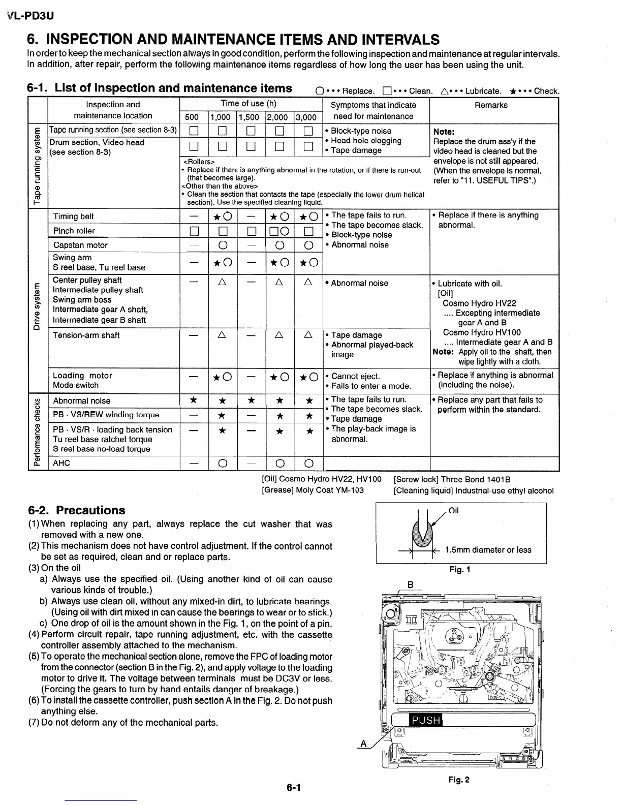
c) One drop of oil is the amount shown in the Fig. 1, on the point of a pin.
(4) Perform circuit repair, tape running adjustment, etc. with the cassette
controller assembly attached to the mechanism.
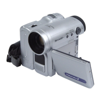
(5) To operate the mechanical section alone, remove the FPC of loading motor
from the connector (section B in the Fig. Z), and apply voltage to the loading
motor to drive it. The voltage between terminals must be DC3V or less.
(Forcing the gears to turn by hand entails danger of breakage.)
(6) To install the cassette controller, push section A in the Fig. 2. Do not push
anything else.
(7) Do not deform any of the mechanical parts.
Oil
1.5mm diameter or less
I I
Fig. 1
A
Fig. 2
6-1