9-3. How to operate with the circuit board without the cassette controller assembly.
In this
method,
if
the procedure is followed
incorrectly
there is danger
of damaging
the
mechanism and the
tape, so except in
special
cases,
such as when measuring the VSR torque, do
not
perform this procedure. Normally operate this unit with the cassette
controller
assembly attached.
Be sure
to follow each
caution
mentioned.
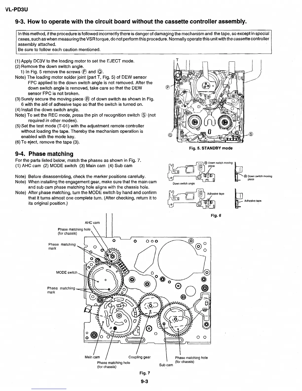
(1) Apply DC3V to
the
loading motor to
set
the EJECT mode.
(2) Remove
the down
switch
angle.
1)
In Fig. 5 remove the
screws @ and @.
Note) The loading motor solder joint (part T, Fig. 5) of DEW sensor
FPC applied
to
the
down
switch angle is not removed. After the
down switch
angle is
removed, take care so that the
DEW
sensor FPC is
not broken.
(3) Surely secure the moving piece @ of
down
switch
as
shown in Fig.
6 with the aid of adhesive tape so that the
switch is
turned on.
(4) Install the
down switch angle.
Note) To set the REC mode, press the pin of
recognition
switch @ (not
required in other modes).
(5) Set
the test mode (T-01) with the adjustment remote controller
without
loading
the tape. Thereby the mechanism operation is
enabled with the mode key.
(6)To eject, remove the tape (3).
9-4. Phase matching
Fig. 5. STANDBY mode
For the parts listed below, match the phases as shown in Fig. 7.
(1) AHC cam (2) MODE switch (3) Main cam (4) Sub cam
pm m@ F;switchmoving 1
, ,
Note)
Note)
Note)
Before disassembling, check the marker positions carefully.
When installing the engagement gear, make sure that the main cam
and sub cam phase matching hole aligns with the chassis hole.
After phase matching, turn the MODE switch by hand and confirm
that it turns almost one complete turn. (After checking, return it to
its original position.)
AHC cam
I I
Phase matching hole
(for chassis)
\ \
I I
Phase
mark
M
Phase
mark
Down switch angle
@I Down switch moving
piece
Fig. 6
Main cam
I
Coupling gear
Phase matching hole
(for chassis)
Fig. 7
I
Phase matching hole
(for chassis)
Sub cam
9-3