VL-PD3U
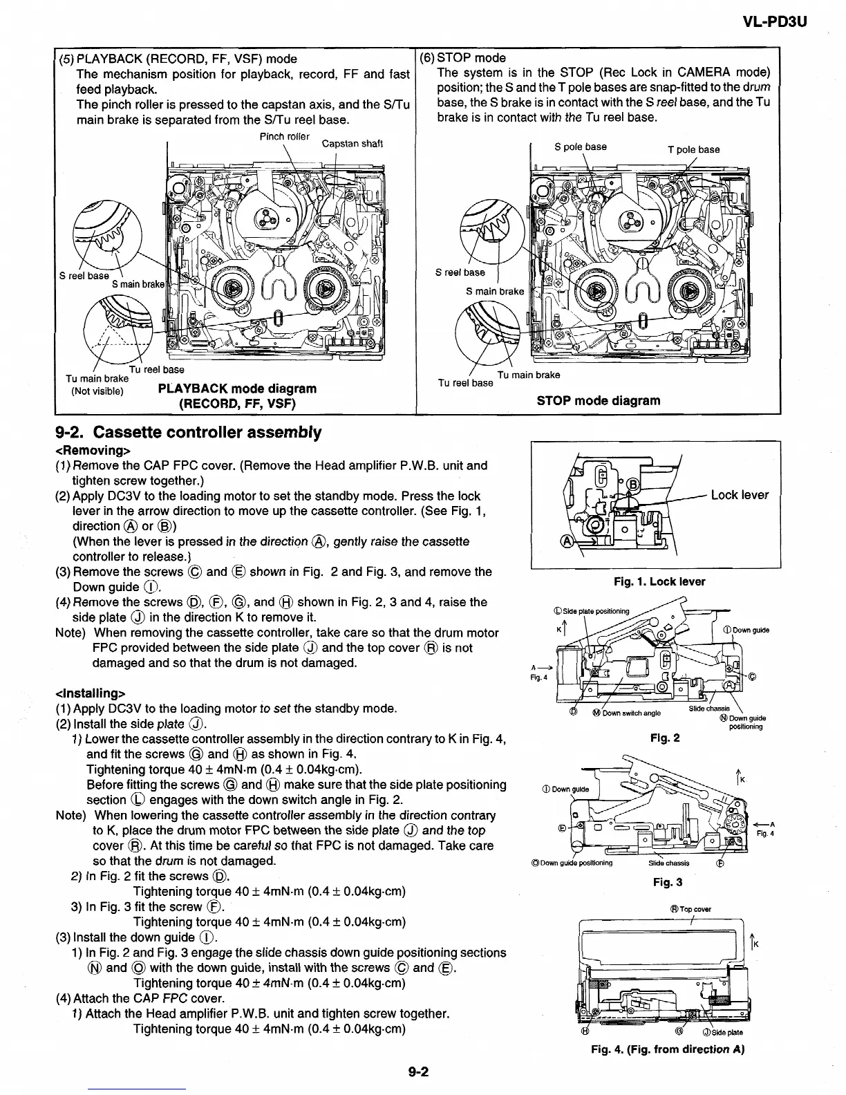
(5) PLAYBACK (RECORD,
FF, VSF)
mode
(6)
The
mechanism
position
for
playback, record,
FF and fast
feed
playback.
The pinch roller
is
pressed
to the capstan
axis, and
the
S/Tu
main
brake is
separated
from
the SITU reel base.
Pinch roller
\
Capstan
shaft
I
SI
Tu
main
brake
(Not visible)
PLAYBACK mode
diagram
(RECORD. FF, VSFI
STOP mode
The
system
is in the STOP (Ret Lock in CAMERA mode)
position;
the S
and the T pole
bases
are snap-fitted to
the drum
base,
the
S
brake is in
contact
with
the
S
reel
base,
and
the
Tu
brake
is
in
contact with the
Tu reel base.
Tu reel
base
STOP
mode diagram
9-2. Cassette controller assembly
<Removing>
(1) Remove the CAP FPC cover. (Remove the Head amplifier P.W.B. unit and
tighten screw together.)
(2) Apply DC3V to the loading motor to
set the standby mode. Press the lock
lever in the arrow direction to move up the
cassette controller. (See Fig. 1,
direction
@ or @)
(When the lever is pressed in the direction @, gently raise the cassette
controller to release.)
(3) Remove
the screws 0 and @ shown
in Fig. 2
and Fig. 3, and remove the
Down guide @.
(4) Remove the screws 0, 0, @ and @I shown in Fig. 2, 3 and 4, raise the
side plate @ in the direction K to remove it.
Note) When removing the cassette controller, take care so that the drum motor
FPC provided between the side plate
@ and the top cover @I is
not
damaged and so that the drum is not damaged.
&stalling>
(1) Apply DC3V to the loading motor to set the standby mode.
(2) Install the side plate
@
1) Lower the cassette controller assembly in the direction contrary to K in Fig. 4,
Lock lever
Fig. 1. Lock lever
@/Down switch
angle
Slide chassis \
@I
Down
guide
positioning
Fig. 2
and fit the screws @ and @I as shown in Fig. 4.
Tightening torque 40 +, 4mNom (0.4 +, 0.04kgcm).
Before fitting the screws @ and @I make sure that the side plate positioning
section @ engages with the down switch angle in Fig. 2.
Note) When lowering the cassette controller assembly in the direction contrary
to K, place the drum motor FPC between the side plate @ and the top
cover @. At this time be careful so that FPC is not damaged. Take care
so that the drum is not damaged.
@ Dow
+A
Fig. 4
0
Down guide positioning
Slide chassis
2) In Fig. 2 fit the screws @$.
Fig. 3
Tightening torque 40 Ifi 4mN-m (0.4 & 0.04kgcm)
3) In Fig. 3 fit the screw 0.
Tightening torque 40 + 4mN.m (0.4 + 0.04kgcm)
(3) Install the down guide 0.
1) In Fig. 2 and Fig. 3 engage the slide chassis down guide positioning sections
@I and @I with the down guide, install with the screws @ and @.
Tightening torque 40 + 4mN-m (0.4 + 0.04kgcm)
(4)Attach the CAP FPC cover.
@ Top cover
f===ib
1) Attach the Head amp1ifier’P.W.B. unit and tighten screw together.
Tightening torque 40 + 4mN.m (0.4 + 0.04kgcm)
92
I
@Side
plate
Fig. 4. (Fig. from direction A)