L-PDl U
ADJUSTING THE ELECTROMAGNETIC CONVERSION
CIRCUIT SYSTEM
I
I
Note:
I
During the adjustment of the electromagnetic conversion circuit system, keep R404 out 1
of operation.
I
1. PLL VCO adjustment
I
[Procedure]
I
1)Playback the alignment tape (or a self-recorded tape).
1 1) During Circuit board (Main)
replacement
2)Call the adjustment mode (V-ADJ).
I
2) During E*PROM replace-
3)Set the address to “2C”, and call the data.
I
ment
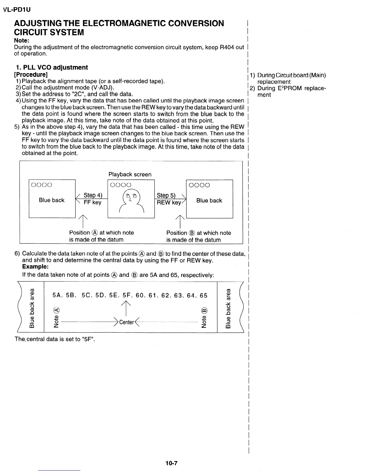
4) Using the FF key, vary the data that has been called until the playback image screen 1
changes to the blue backscreen. Then use the REW keytovarythedata backward until
1
the data point is found where the screen starts to switch from the blue back to the I
playback image. At this time, take note of the data obtained at this point.
5) As in the above step 4), vary the data that has been called - this time using the REW 1
I
key - until the playback image screen changes to the blue back screen. Then use the 1
FF key to vary the data backward until the data point is found where the screen starts I
to switch from the blue back to the playback image. At this time, take note of the data I
obtained at the point.
0000
Blue back
Playback screen
0000
0000
Step 5)
REW key
Blue back
Position @ at which note Position @ at which note
is made of the datum is made of the datum
6) Calculate the data taken note of at the points @ and @I to find the center of these data, I
and shift to and determine the central data by using the FF or REW key.
Example:
If the data taken note of at points @ and @ are 5A and 65, respectively:
2
2
5A. 5B.
5C.
5D.
5E. 5F. 60. 61. 62. 63. 64.
65
Y
2
13
0
<
0
2
5 a>
m
z
ij
Thecentral data is set to “5F”.
I
I
I
I
I
I
I
I
I
I
I
I
I
I
I
1 o-7