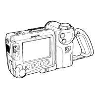
VL-SDSOU
(Wiring
board
diagram:
POWER Side A)
.
3.
SHUT
OFF adjustment
Measuring
instrument
Digital
voltmeter
Address
06, OE
Adjustment
rating
6.OOV + 50mV
Test point
TL9942(+),
TL9945(-), TL9951
Mode
CAM
Tape
Recordable
tape
Test signal
Procedure
1
GND
1
1)
Set
TL9951
to
(
SND.
2)
Load a recordable tape.
3)
Set
the
camera mode. Then, press the REC
key.
4) Press
the “Continuous
Press” and
then the
“Test
Mode Select” on the
remote
control to enter the
test
mode (01
blinks).
5)
Select 03 with REW or FF and
then
press
the PB key. (03 blinks ti
03
lights)
6) Observing
the
power voltage
from TL9945(-), set it so that TL9942(+) obtains 6.OOV
f 50mV.
7) Press the PB key
on the main unit.
Turn off the power and the adjustment is completed.
ADJUSTING THE ELECTROMAGNETIC CONVERSION CIRCUIT SYSTEM
1. PLL VCO adjustment
Mode
VCR ADJ mode
Procedure
1) Playback the alignment tape (or
a self-recorded tape).
I I
2) Call the adjustment mode
(V-ADJ).
3) Set to
address “24” and then change the screen
with FF/REW key until
the playback screen appears (the
screen full of block noise is OK).
Examples
l
During E2PROM replacement.
2. Phase and equalizer adjustment + (Performed in the VCR mode)
Mn&
1
VCR ADJ
mode
. ..___
_ - ..- _ ..___
Procedure
1) Load a
self-recorded
tape into the deck.
2) After playback for 3 minutes, select the test mode OF using the remote control for adjustment to start the
automatic adjustment. (The following sequence is automatically performed.)
Select and fix the TEST MODE OB on the adjustment remote control.
4) Manual adjustment method (video adjustment mode)
l
Perform this adjustment with the self-recording/playback in the LP mode.
For phase, vary the data for the address 26and 28, and for equalizer, vary the data for the address 25 and 27
to set the error rate is made as small as possible.
WJ w r;;:Y:z~a~ion error ~~~~~~ ~;;~~~~;
Examples
l
During mechanism replacement.
l
During circuit board (Main) replacement.
l
During E*PROM replacement.
1 o-7