WF-971T
NOTES ON SCHEMATIC DIAGRAM
•
Resistor:
To differentiate the units of resistors, The symbol as K and
Mare used: the symbol K means 1000 ohm and the symbol
M means 1000 kohm and the resistor without any symbol
is an ohm resistor. The resistor designated "Fusible" is a
fuse type resistor.
•
Capacitor:
To indicate the unit of capacitor, a symbol P is used: this
symbol P means pica-farad and the unit of the capacitor
without such a symbol is microfarad. As to electrolytic
capacitor, the expression "capacitance/withstand voltage"
is used.
(CH),(RH),(UJ): Temperature compensation
(ML): Myiar type
(S): Styrol type
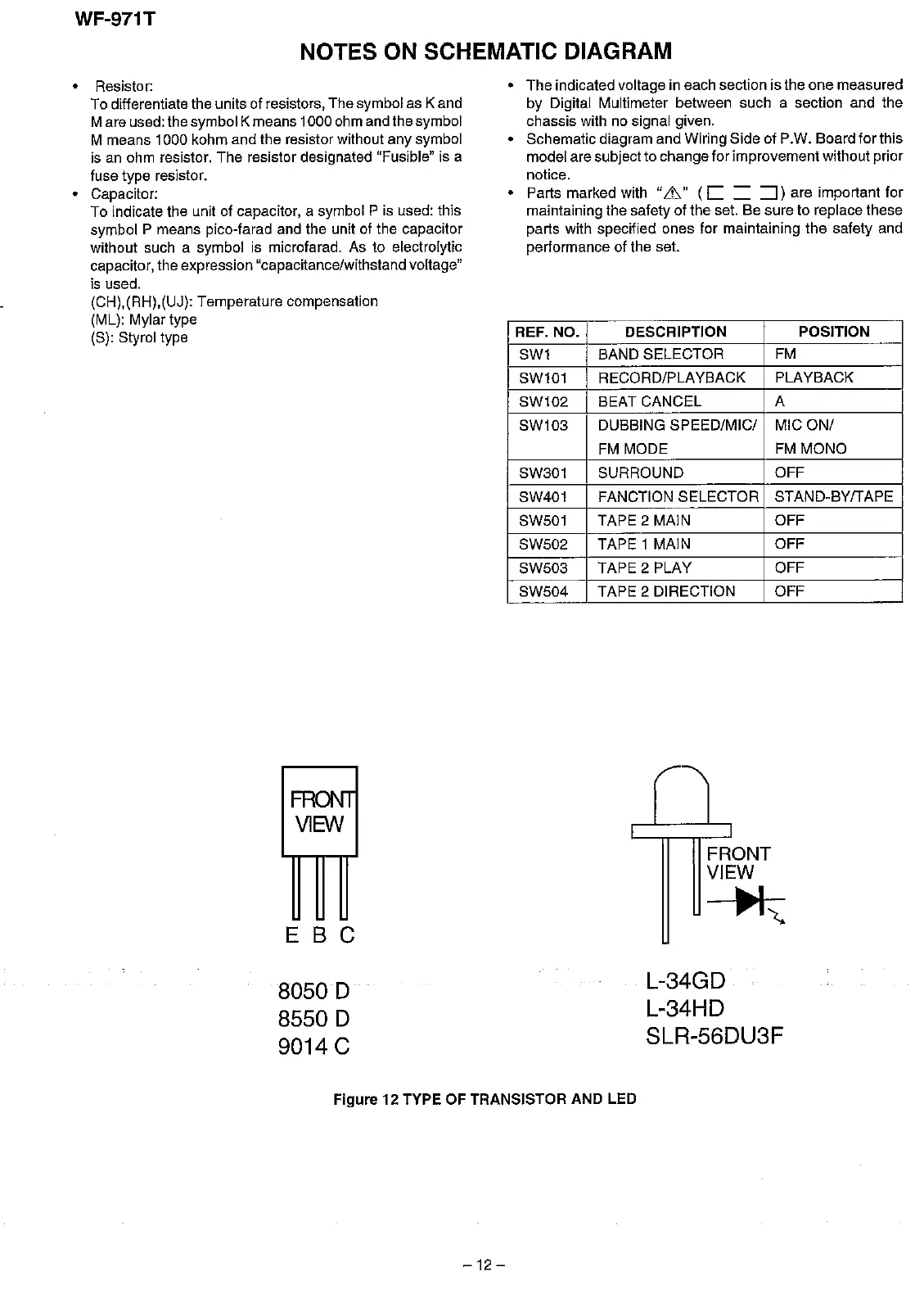
FA
V1BN
E B C
80500
85500
9014 C
• The indicated voltage in each section is the one measured
by Digital Multimeter between such a section and the
chassis
with
no
signal
given.
• Schematic diagram and Wiring Side of P.W. Board forthis
model are subject to change for improvementwithout prior
notice.
• Parts marked with
",Ih"
(C
=
::J)
are important for
maintaining the safety of the set. Be sure to replace these
parts with specified ones for maintaining the safety and
performance of the set.
REF. NO. DESCRIPTION
POSITION
SW1
BAND SELECTOR FM
SW101
RECORD/PLAYBACK PLAYBACK
SW102 BEAT CANCEL A
SW103
DUBBING SPEED/MIG/ MIG ON/
FM MODE FM MONO
SW301 SURROUND
OFF
SW401
FANCTION SELECTOR STAND-BYfTAPE
SWS01
TAPE 2 MAIN OFF
SWS02
TAPE 1 MAIN OFF
SWS03 TAPE 2 PLAY
OFF
SWS04
TAPE 2 DIRECTION
OFF
FRONT
VIEW
~
L-34GD
L-34HD
SLR-56DU3F
Figure 12 TYPE OF TRANSISTOR AND LED
-12
-