WF~97:tT
:~';~:\-)
';':
''',
t
C02.}
x3
Special Screw
1'-TA:PE21
;,j-
j
Playback
Head'-
t
I TAPE'2 1 " '
.1
Pillch. Roller'
..
--
,195f
,,,i).
,
Pinch
Roller
Pawl" •..
...........
.,,,
'(l)
:JI:T'APElf;!
(AI)
,,1·.
i
, ,·,
..•.
,.0:'1
02x3mm, ,J
',-,
,,~'-,)
hJ
.'
·,·;CRecord/Playback
-Head
.
<_1.'-,.';
I,
',1
Figure 5-1
Figure
5-2
Motor
Figure
5-4
.Figure
5"'3
i.: i
, ):'.:
~l
iI~:d'J~)",'i');)
;".
(81-)-1<1-
02x6mm
Hook
~A,2)
,,:;....'. . ,
WW
·:::
,-
"
" ,.
,
t
[TAPE
1 I
'in
Pinch·Rolier
- @ " . (Cl).·.·.· .
",,'
"'j
',J
PinchRoller
Pawl
REW/
FF
Belt REW
/FF
(E3) xl ClutchAss'y
I
TAPE
1 I
Mater
,',"
ITAPE21
Frywheel
REW/ FF
Belt
(E3)
xl
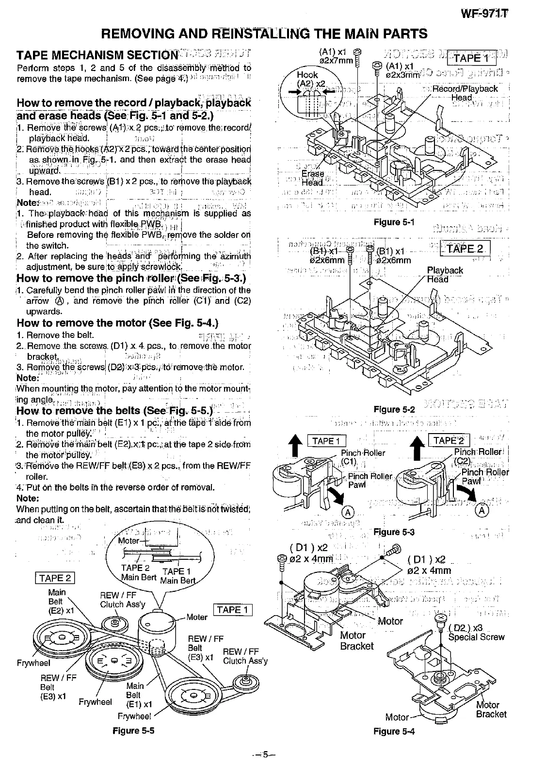
REMOVING AND
~EINSr~LlING
THE MAIN PARTS
TAPE
MECHANISM SECTIOllj:J
Perform steps 1, 2 and 5 of the dis!lssembly""methbd to
remove the tape mechanism. (See page
4';)
J::
'i.""'1·I">:,
'
':'
-'.
;-:';
':-l'
':~
-~:'"
:1
How
to remove the record I playback; playback
and-e-iaseheads
(See
Fig.5~1·
and5~2.)
...
',I. Remove
thif~crews!
(,I\I}x~
pCS:;LtO'
remove.the:recordi
i
playbadffl6:ad.
i
~'iL';)i]'
.
,_
...
'_',
__
..
'
..
_,
_, '._ .. 1 .. _
.,
_
....
_
...
,I
,2.Rembv.em;e..
hQiqk~(A2P(2pts:;toW~rd
the
tef1terpositi~rl
;
a.~;,~.~,o",,~}n;
~iq,)5,1.
and then extia9t the erase head
.. upward. __
..1_
_ . __ 1
'3. Remove
thescrews
:(Bl)
x 2 pcs., to remove the
plaYbae~
'head.
-;:;:)i';
: ",;YT ::-;;
,',"<)
iNote:~::<';;:i'-:'
":'-,i,]::.;
):-1
!
,1:1,>:'))
';:
. ,1i,:.:';, ,
.".
,I. The-playbaclc.
hea~
of this
m~pqi'.~i.s,m
is supplied as
.
;:finished product with
f1exiplE\;Pi!V,!;l,',
Hi I
Before removing the flexible PWB,.:re"love the solder on
i the switch.
\.-
...-
-
......
",--
_..
2. After replacing the 'heads'
lliiiJ'·ila.ri6r~ing
the"iizirh~tJ1
~.
"',
-."
'''',
. ' t l .:. ':_.' '."
~
I
adjustment, be
sure:t(j~applyscrewIQck:i'
How
to remove the pinch ,roUetl
l(See,Fig.
15-3.)
il.
Carefully bend the pinch rollerp,,"wl
h,'
the direction of the
.
arrow
®,
and remove the pinch
ron'er
(C1
rand
(C2)
upwards.
How to remove the motor (See Fig. 5-4.)
1. Remove the beit.
''liT:'!:
2..Remove
the
screws,
(Dl)
x 4 pcs.,
toremovelhe
motor
bracket, ,_', ,.,
:'
~h;;~'j:'i
i~.:~'
,
3.
Rem~v~'
ik~'~crewsi
(D2)JxJ3:pcs'iitcYramovethe motor.
,
i,lJ..':)-,),I,
',.1
" .
Note:
When
ffi,!untiqg themotor, pay attention to the m6t6rmount;
'ing
,argl~~;:
;'::'1'
j":'1
i
;
'",")
!_~:'
i-
-;.,,;.
How
to remove the belts (See Fig. 5-5.)
..."
'.
'1.
Remo~ethe"rriaiil
b~lt
(El)
x 1
pc:,aitHe
lapefs1defro"l
. the motor
pulle\C:
..
".
":".
.
2.
Remove the:ri1airibelt (E2).x:li pc.cat the tape 2 slde.from
therhotor'plilley.
'3.
m;rhove
the REW/FF belt,(Eii)
1<2.
pcs., from the REW/FF
roller.
4:PUf
on the beits in the reverse order of removal,
Note:
When putting on the belt, ascertain
thatthe
5eitisnot
twisted,
.and clean it.