13
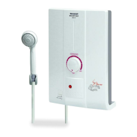
1. Remove the body in accordance with “REMOVE OF BODY”.
2. Remove the nut holding the volume SW. to the tting plate.
3. Remove 2 screws holding the tting plate to the back cover.
4. Cut off the volume SW. lead wire at PCB control ass’y.
5. Now the volume SW. ass’y is free.
REMOVE OF VOLUME SW. ASS’Y
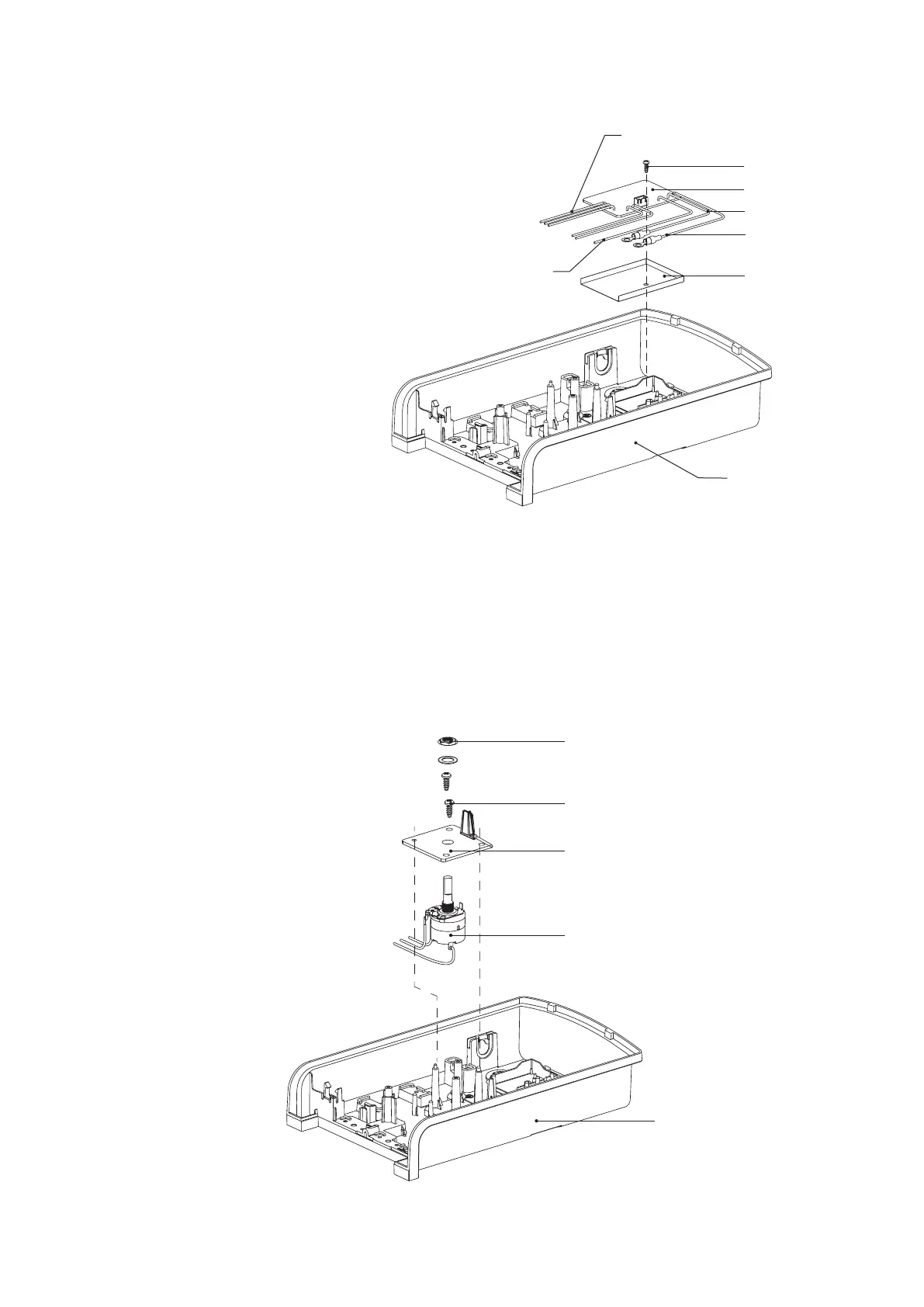
1. Remove the body in accordance with “REMOVE OF BODY”.
2. Disconnect reed SW. lead wire from PCB control ass’y.
3. Remove the screw holding the PCB control ass’y.
4. Cut off the volume SW. lead wire at the PCB control ass’y.
5. Disconnect the white lead wire from the triac and the
breaker.
6. Disconnect lead wire red from the triac.
7. Remove 2 screws holding lead wire brown
and lead wire black from heater tank.
8. Now the PCB control ass’y is fee.
REMOVE OF PCB CONTROL ASS’Y
Volume SW.
Fitting plate
Screw
Nut
Back cover
Fig. 26
Fig. 27
Back cover
Insulation sheet
White lead wire
PCB control ass’y
Brown lead wire
Black lead wire
Screw
Volume SW. lead wire