Do you have a question about the Sharp XL-505 and is the answer not in the manual?
| Brand | Sharp |
|---|---|
| Model | XL-505 |
| Category | Stereo System |
| Language | English |
General specifications of the audio system.
Technical details of the amplifier.
Technical details of the tuner.
Technical details of the CD player.
Technical details of the cassette deck.
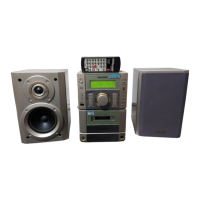
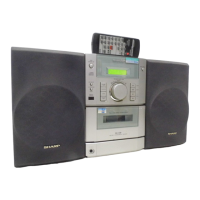
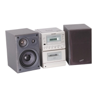
Identification of parts on the front of the unit.
Identification of parts on the rear of the unit.
Details of the CP-505B speaker components.
Identification of parts on the remote control.
Steps to prepare the unit for operation.
Instructions for setting the unit's clock.
Procedure to reset the system microcomputer.
Basic setup instructions for the audio system.
Steps for playing a compact disc.
Instructions for recording audio from CDs.
How to play cassette tapes.
Steps for operating the radio tuner.
Usage of the remote control.
Important warnings and precautions for usage.
How to adjust sound settings.
Safety and performance notes before disassembling.
Disassembly steps for the XL-505/505C model.
Disassembly steps for the CP-505B model.
Procedures for removing the CD mechanism.
Steps to remove the optical pickup unit.
Adjustments for the tape mechanism section.
Adjustment procedures for the tuner section.
Adjustment for signal detection in the tuner.
Adjustment for AM intermediate and radio frequency.
How to enter test mode for tuner adjustment.
Adjustment of FM mute level.
Adjustment procedures for the CD player section.
Details on automatic adjustment features.
How to access different test modes.
Steps for entering and operating CD test mode.
Block diagram of the microcomputer and related circuits.
Block diagram of the servo amplifier.
Block diagram of servo and signal control IC.
Block diagram of the PLL controller for tuner.
Block diagram of the audio processor.
Block diagram of the power amplifier.
Schematic of the front end tuner circuitry.
Schematic of the audio processor section.
Schematic of the power amplifier section.
Schematic of the CD servo PWB.
Wiring diagram for the main Printed Wiring Board.
Wiring diagram for the power supply PWB.
Voltage table for IC101.
Voltage table for IC303.
Voltage table for IC401.
Voltage table for IC701.
Voltage table for IC801.
Voltage table for IC802.
Voltage table for IC102.
Voltage table for IC301.
Voltage table for IC302.
Voltage table for IC804.
Voltage table for IC601.
Explanation of resistor marking codes.
Explanation of capacitor marking codes.
Identification of common transistor and LED types.
Troubleshooting steps when the CD player fails to operate.
Pin functions for the System Microcomputer (Part 1).
Detailed pinout and functions for the IC802 Servo/Signal Control IC.
Block diagram of the Servo/Signal Control IC.
Detailed pinout and functions for the IC801 Servo Amplifier IC.
Block diagram of the Power Amplifier IC.
Diagram showing the LCD segments and common connections.
Instructions for ordering replacement parts.
Guide to understanding component part codes.
List of transistors used in the unit.
List of diodes used in the unit.
List of capacitors used in the unit.
List of resistors used in the unit.
List of parts for the CD mechanism assembly.
List of parts related to the unit's cabinet.
List of included accessories and packing materials.
List of parts used for packing the product.
List of parts for the speaker boxes.
Exploded view of the CD mechanism components.
Exploded view of the unit's cabinet and internal components.
Exploded view of the speaker assembly.
Recommended settings for switches and knobs during packing.