SECTION 7 GAS PURGE
36
263-13236
7
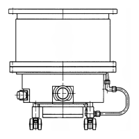
The turbo molecular pump incorporates a gas purge port (Fig. 2-1 (2)). Gas purging is not
required for ordinary evacuation. However, a purge gas flow is recommended to protect the
bearings during evacuation of large quantities of corrosive gas during an etching process, for
example. An inert and chemically stable non-condensing gas is most suitable for the purge gas.
Nitrogen is the most popular purge gas. A purge gas flowrate between 20 and 30 mL/min is
appropriate.
Please consult your shimadzu representative, during evacuation of corrosive gas.
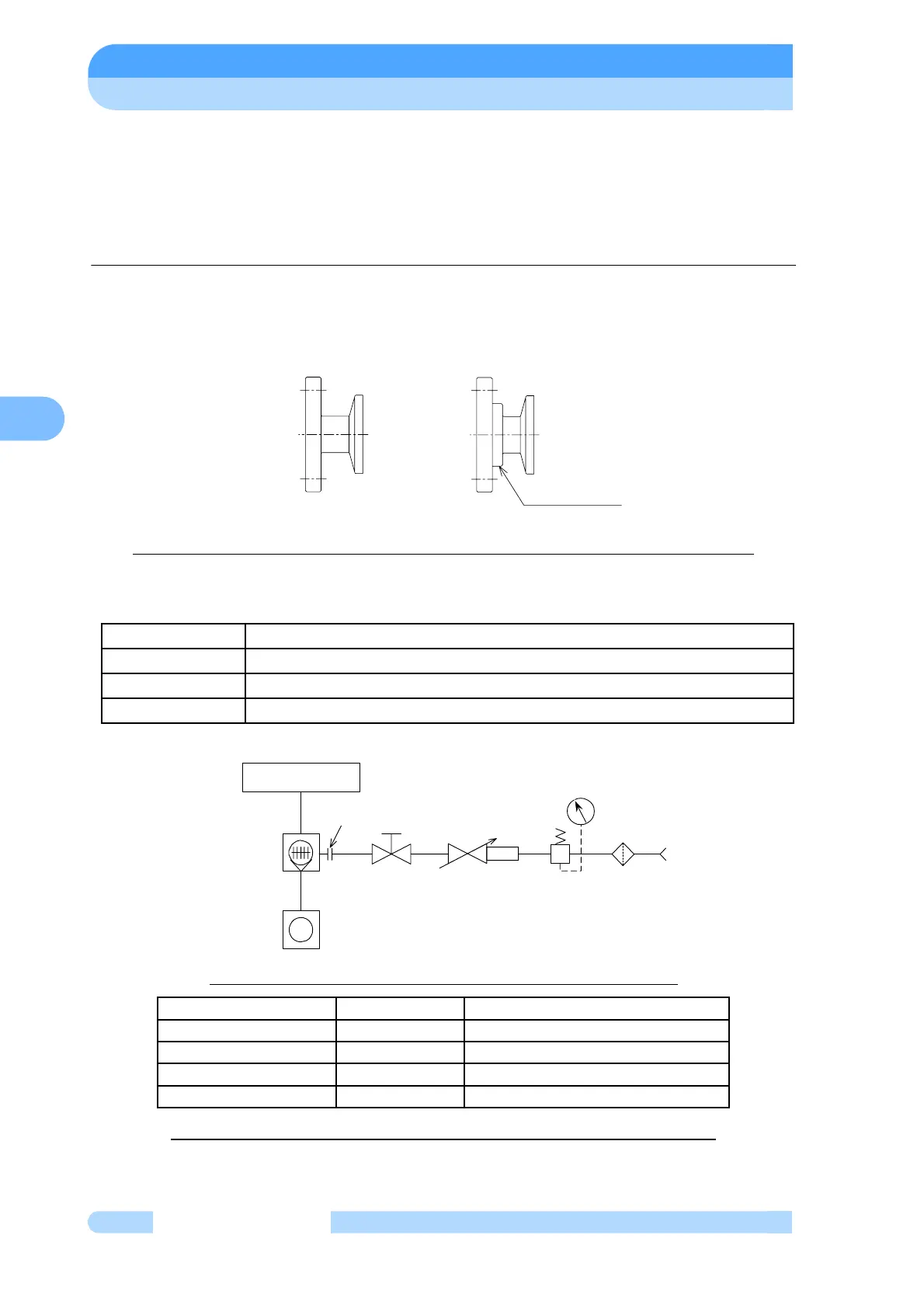
The gas-purge adaptor is available without an orifice (recommended) or with an orifice (option).
Refer to Fig. 7-1 to check whether the gas-purge adaptor attached to the purchased pump
incorporates an orifice. Connect the gas-purge adaptor correctly, according to the piping
diagrams below. The diagram shows the KF10 joint, but the method of recognizing the orifice is
the same for all joints.
Without orifice
With orifice
Fig. 7-1 How to Recognize if the Gas-purge Adaptor Incorporates an Orifice
Fig. 7-2 shows an example of a gas-purge piping diagram. Use a filter element size of 5 μm,
or less. Use a stop valve to start and stop the purge gas flow.
Fig. 7-2 Gas Purge Method (diameter of orifice is φ0.5mm)
Table. 7-1 Table of Gas-purge Ports (diameter of orifice is φ0.5mm)
Gas supply
20
± 10 kPa gauge pressure (nitrogen gas)
Gas feed start After starting backing vacuum pump; before evacuating process gas
Gas feed stop
After exhausting process gas sufficiently; before stopping backing vacuum
Type of gas Nitrogen gas or argon gas (Purity > 99.99%)
Joint PART No. Description
KF10 262-77592-19 GP ADAPTOR, 0.5 KF10
UJR 6.35 263-14770 GP ADAPTOR, 0.5 UJR
SWAGELOK
φ6.35
263-14771 GP ADAPTOR, 0.5 SWG
4-VCR 263-14772 GP ADAPTOR, 0.5 VCR
Orifice insertion
position
PURGE PORT
CONTROL VALVE
VACUUM CHAMBER
TURBO MOLECULAR
PUMP
BACKING VACUUM PUMP
FILTER
VALVE
REGULATOR
GAS
SOURCE
FLOWMETER WITH