3
33
3
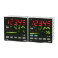
MAC5 panel cutout (unit: mm) Applicable thickness is 1.2 to 2.8mm
Note: Proximity attachment by a single hole is possible only in the case of
horizontal direction. When an apparatus that was attached in vertical direction
is removed, a dedicated detachment tool is required.
3
33
3-
--
-4. Wiring
4. Wiring4. Wiring
4. Wiring
「
「「
「
WARNING」
」」
」
◎Do not turn on electricity while wiring to avoid an electric shock.
◎Do not touch a terminal or live part while turning on electricity.
(1) Make sure that wiring operation is properly done in line with a terminal wire
diagram of section 3-5.
(2) Choose a suitable compensation lead wire in the case of
thermocouple input.
(3) In the case of resistance bulb input, resistance value of each
lead wire must be less than 5Ω and that of three lead wires must
be equal.
(4) Do not wires an input signal line inside of an electric wire pipe
or a duct same with the high voltage line.
(5) Shield wiring (single point grounding) is effective against static
induction noise.
(6) Wiring twisted at equal short intervals is effective against
electromagnetic induction noise.
A
AA
A
B
BB
B
C
CC
C
D
DD
D
E
EE
E
A B C D E
MAC5A 92 92 96min 96min (96*N-4)
MAC5B 92 45 48min 96min (48*N-3)
MAC5C 68 68 72min 72min (72*N-4)
MAC5D 45 45 48min 48min (48*N-3)
+
++
+0.8
—
——
—0
+
++
+0.8
-0
+
++
+0.6
-0
+
++
+0.6
-0
+
++
+0.8
-0
+
++
+0.6
-0
+
++
+0.7
-0
+
++
+0.7
-0
+
++
+0.7
-0
+
++
+0.6
-0
+
++
+0.6
-0
+
++
+0.6
-0
OUT2/EV3/DI4
7
8
9
10
11
12
13
14
15
16
17
18
EV2
EV1
INPUT
L
N
POWER
OUT1
90-264V AC
50/60Hz 9VA
+
-
A
B
B
+
-
+
-
CONTACT:240V AC 2A
SSR DRIVE:12V DC 20mA
CURRENT:4-20mA DC
CONTACT:240V AC 2A
SSR DRIVE:12V DC 20mA
EV3
:240V AC 2A
240V AC 2A
240V AC 2A
COM
4
5
6
10
11
12
13
14
15
EV2
EV1
L
N
POWER
OUT1
90-264V AC
50/60Hz 9VA
OUT2/EV3/DI4
INPUT
+
-
A
B
B
CONTACT:240V AC 2A
SSR DRIVE:12V DC 20mA
CURRENT:4-20mA DC
+
-
+
-
CONTACT:240V AC 2A
SSR DRIVE:12V DC 20mA
EV3
:240V AC 2A
240V AC 2A
240V AC 2A
COM
7
8
9
1
2
3
4
5
6
7
8
9
10
11
12
EV2
EV1
L
N
POWER
OUT1
90-264V AC
50/60Hz 9VA
OUT2/EV3/DI4
INPUT
+
-
A
B
B
CONTACT:240V AC 2A
SSR DRIVE:12V DC 20m
CURRENT:4-20mA DC
+
-
+
-
CONTACT:240V AC 2A
SSR DRIVE:12V DC 20m
EV3
:240V AC 2A
240V AC 2A
240V AC 2A
COM
Terminal arrangement MAC5D
Terminal arrangement MAC5C
Terminal arrangement MAC5A,B
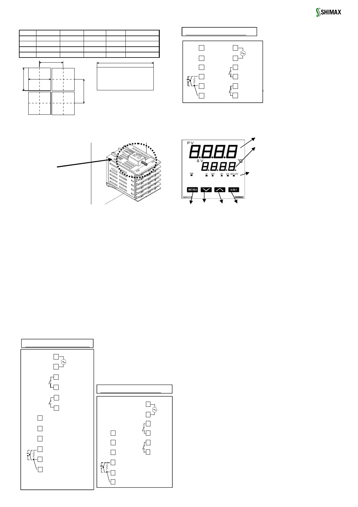
4. Description of front panel
4. Description of front panel4. Description of front panel
4. Description of front panel
4
44
4-
--
-1. Names of front panel.
1. Names of front panel.1. Names of front panel.
1. Names of front panel.
4
44
4-
--
-2. Explanation of
2. Explanation of 2. Explanation of
2. Explanation of
front panel section
front panel sectionfront panel section
front panel section
① : Display of measured value (PV) (red) Measured value (PV) and type of
setting is displayed on each setting screen.
② : Display of target value (SV) (green)
Target value and set value are displayed on each setting screen.
③:Monitor LED
(1) RUN monitor LED RUN (green)
If RUN is performed with RUN key, operation mode1 screen, external
control input (DI), and communication, it lights up, and put out
by standby (reset). It blinks, if a manual output is chosen in
output monitoring screen or external control input (DI).
(3) Auto tuning operation monitor LED AT (green)
If AT is chosen in ON or external control input (DI), blinks during
AT execution. Lights up when AT is on standby, and puts out
with AT automatic termination or release.
(4) control out put 1 monitor LED OUT (green)
At the time of a contact or a voltage pulse output, the it lights up
with ON and lights off with
OFF. Lights off with 0% power output, and lights up with 100%
power.
And blinks in intermediate ratio.
(5) Event output monitors LED EV1 and EV2 (yellow)
Lights up when the allotted event output turns to ON.
(6) Control out put 2/event output 3 monitors LED OUT2/EV3 (yellow)
When control output 2 is chosen, it operates like control output 1
monitor LED does.
When event output 3 is chosen, it operates like event output
monitor LED does.
④: Key-switch section
(1) (MENU)key
Press this key to move onto the next screen among the screens.
Press (MENU) key for three seconds on the basic
screen, then it jumps to the lead screen of Mode 1. Press key
for three seconds on the lead screen of each Mode screens, then
it jumps to the basic screen.
Press key for three seconds on the lead screen of (2) (DOWN) key
Press (DOWN) key one time, and the shown value decreases
by one numerical value.
One time press of key decreases by one numerical value. By
pressing the key continuously, the value as well consecutively
decreases. A decimal point of the smallest digit blinks at this
time. This shows that a setting change is in progress.
「Note」: If input type is
thermocouple or voltage, errors
may occur when terminal 5 and
terminal 6 terminal are short-
circuited
3
33
3-
--
-5. Terminal arrangement diagram
5. Terminal arrangement diagram5. Terminal arrangement diagram
5. Terminal arrangement diagram
When the thickness of the
panel is different from the
1.2 to 2.8mm,
Attachment available
 Loading...