Mark V 520 Summary Manual
SM - 13
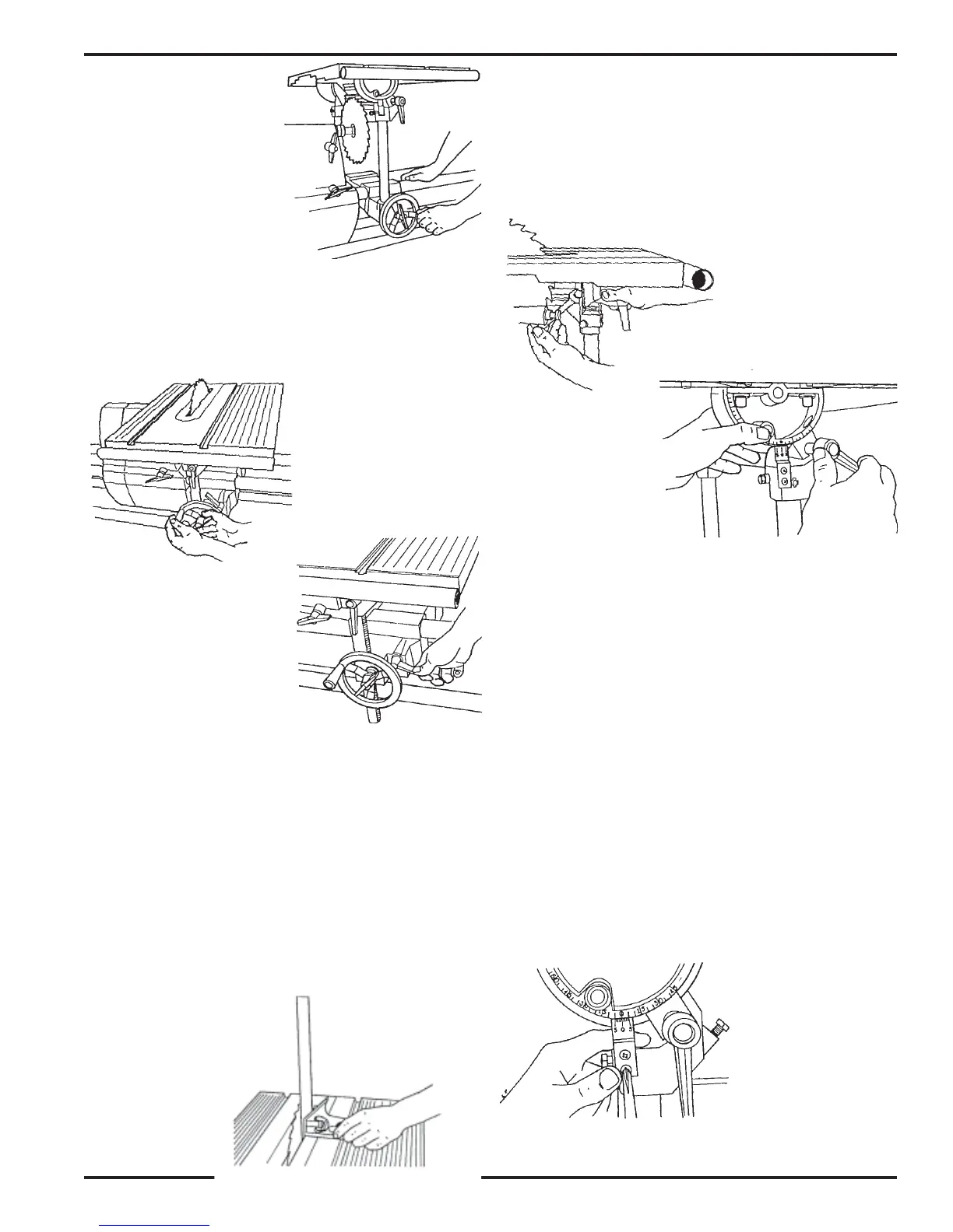
24. Lower the worktable (but not all the way
down) so the saw blade comes through the
slot. Lock the table height, as seen in Figure B-
62.
25. Tighten the carriage lock, as shown in Figure
B-63.
26. Place the combination square against both the
saw blade and worktable, as seen in Figure B-
64. Make sure the square's blade does not
touch a saw tooth and does rest in a gullet
between teeth.
27. If the worktable is not exactly perpendicular
to the saw blade, adjust the worktable so it is
perpendicular to the saw blade, then tighten
the tilt lock.
28. To adjust the 0° stop, simultaneously depress
the table stop pin and use a 1/2" wrench to
adjust the stop bolt. The stop bolt should just
contact the side of the stop pin. Once the stop
bolt is adjusted, the stop pin will "lock" back
when the tilt lock is tightened. See Figure B-
65.
Figure B-61
Figure B-62
Figure B-63
Figure B-66
Figure B-65
Figure B-67
Figure B-64
29. Loosen the tilt lock, move the worktable, then
depress the 0° stop pin until the stop bolt
contacts it. Tighten the tilt lock, and recheck
the setting by repeating Steps 26 through 28.
See Figure B-66. (It is very important to re-
check the setting!)
ADJUST THE TABLE TILT INDICATOR
30. Tighten the table tilt lock and check that the
"0" mark on the indicator aligns with the "0"
mark on the trunnion.
31. To adjust the scale, use a medium Phillips
screwdriver to loosen the two screws which
hold the indicator to the tie bar. See Figure B-
67. Then while holding the indicator in posi-
tion so the "0"s are aligned, retighten the
screws.