SM - 20
Summary Manual Mark V Model 520
The Mark V Model converts to five modes– table
saw, disc sander, drill press, horizontal boring,
and lathe.
NOTE
These Mode Setup procedures assume that there is
nothing mounted to any spindle and all alignments
and adjustments have been completed.
One of the most useful features about the Mark V
is that you can "borrow" angles and setups from
one mode to the other. This greatly improves the
accuracy of your woodworking.
To "borrow" a setup, don't break down the ma-
chine completely as you change from mode to
mode. For example, if you need to cut a miter,
sand it smooth, and then bore for dowels, keep
the table and the miter gauge in the same position
as you move from table sawing to disc sanding to
horizontal boring. This will ensure that your
stock is cut, sanded, and bored precisely the
same. It also saves you setup time.
As you change from one mode to another, keep
these four safety rules in mind:
1. Turn the speed dial to "Slow," then turn off
and unplug the Mark V before you break
down one mode and set up another. Al-
ways have the speed dial set to "Slow." It is
dangerous for both you and your electrical
circuit to start accessories at high speed (i.e.,
the sanding disc can blow fuses at table saw
speed and the lather will throw stock at
rout-shape speed).
2. Make sure that accessories are properly
mounted on the main spindle. The flat on
the main spindle is ground with a "reverse
taper" to keep accessories secured.
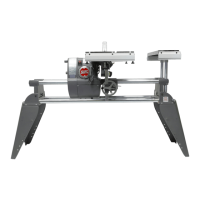
a. To properly mount an accessory,
push it onto the main spindle all the way.
Then use a 5/32" Allen wrench to tighten the
setscrew against the flat of the spindle. (See
Figure B-119.) To make sure the accessory is
securely mounted, rock the accessory back
and forth slightly as you tighten the set-
Figure B-119
Mode Setups
screw and then again after it is tight, while
keeping the spindle from turning. If the
accessory seems to loosen, tighten the set-
screw again until you've removed any "play."
3. Check all locks before turning on the ma-
chine. To properly secure a lock, spin it until
it stops, then tighten it an extra 1/4 turn.
CAUTION
Be careful not to overtighten locks. Overtightening
locks may damage the way tubes, table support tubes,
or other parts of the machine.
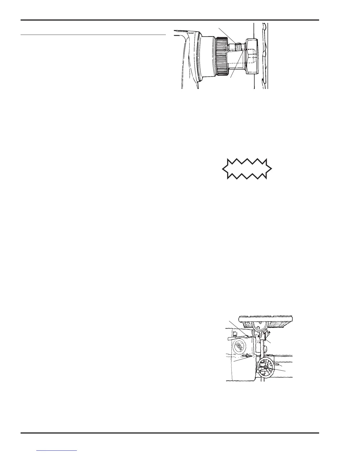
To be sure all locks are as they should be, make a
five-point check before you turn on the Mark V.
With a clockwise sweep of your hand, check each
of these locks in succession: table tilt lock, car-
riage lock, table height lock, headstock lock, and
quill lock. See Figure B-120. The carriage lock
handle must be secured in the horizontal posi-
tion. The quill lock should be loose in the drilling
and boring modes, and for some sanding opera-
tions. In the lathe mode, this procedure becomes
a four-point check, since the table has been re-
moved.
Reverse
taper
Set-
screw
Carriage
Lock
Table height
Quill lock
Head-
stock
Table tilt lock
Figure B-120
When changing from a horizontal to a vertical
position, secure the base lock. When changing
from vertical to horizontal, secure the headrest
lock. If you're mounting accessories in the power
mount or base mount, secure the mount locks.