SM - 16
Summary Manual Mark V Model 520
INSTALL THE TABLE INSERT IN THE
WORKTABLE
46. Place the table insert in the worktable recess.
Use a 5/32" Allen wrench to start both screws.
47. First tighten the rear screw. Then the front of
the insert will be sprung slightly above the
table. Level the insert by placing your hand on
the front of the insert, as in Figure B-79, and
slowly turning the front screw until it draws
the front of the insert flush with the worktable
surface.
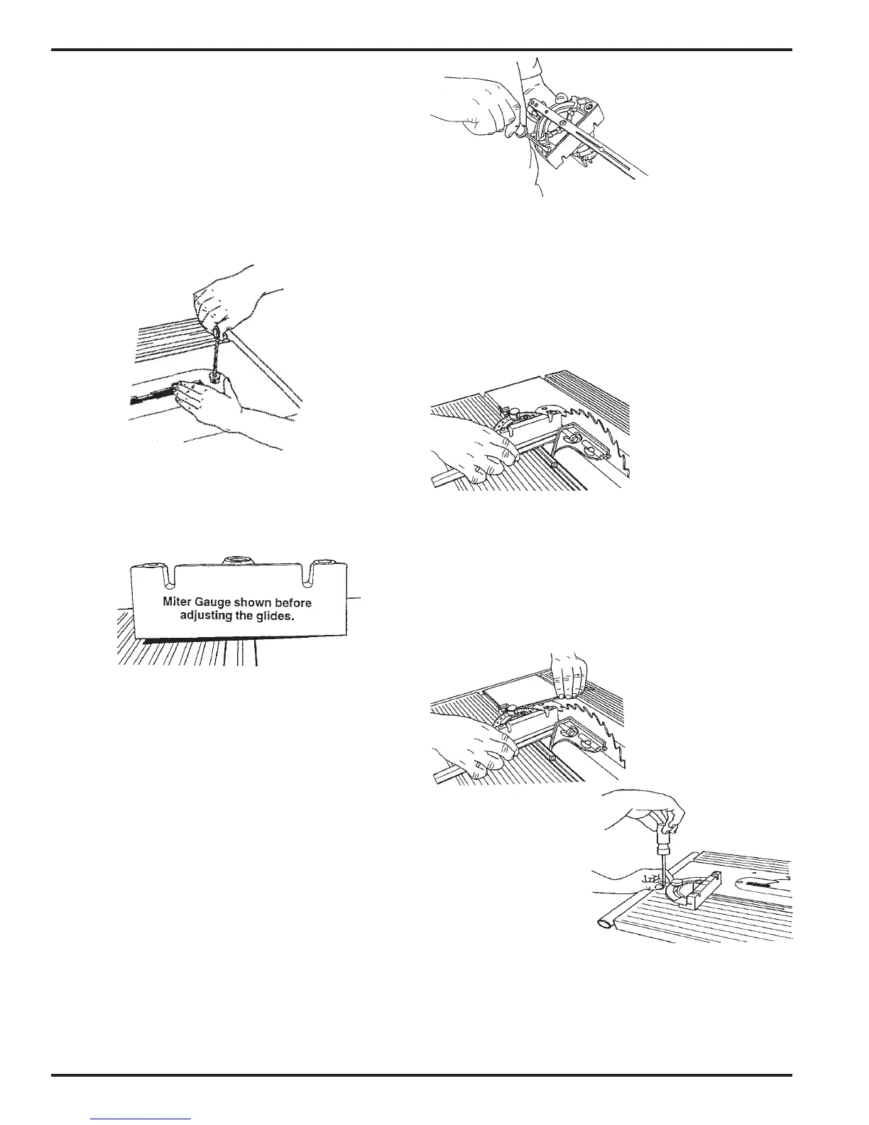
ADJUST THE MITER GAUGE FACE
51. Remove the safety grip from the miter gauge.
Make sure you keep the small, thin washer.
52. Put the miter gauge in the right slot and place
the combination square against the saw blade
and miter gauge face, as seen in Figure B-82.
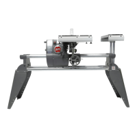
ADJUST THE MITER GAUGE GLIDES
48. Place the miter gauge in the worktable's miter
gauge slot. See Figure B-80.
Figure B-79
Figure B-80
Figure B-81
53. If the miter gauge face is not perpendicular
to the saw blade, do the following:
a. Use a long Allen wrench to loosen the
lock knob (268) and adjust the miter
gauge so it is perpendicular to the saw
blade, then tighten the lock knob. See
Figure B-83.
Figure B-83
Figure B-84
Figure B-82
b. Use a medium screwdriver, loosen the
screw (273) which holds the indicator plate
(275 ), and set its "0" to the miter gauge's
"90". Tighten the screw. See Figure B-84.
49. Check to see if the miter gauge wobbles side-
to-side. Also, slide it back and forth in the slot
to check if the miter gauge scrapes against the
table. If the miter gauge rocks or scrapes the
table, adjust the glides.
50. If the glides need to be adjusted, do the follow-
ing:
a. Remove the miter gauge from the slot and
turn it over.
b. Use a medium screwdriver to screw the
glides in or out, as illustrated in Figure B-
81, so that the glides hold the miter gauge
1/64" to 1/32" off the worktable and the
miter gauge does not rock in the slots.
c. Return the miter gauge to the slot and
recheck and re-adjust it, if needed.