Do you have a question about the ShoreStation SSV50120HS and is the answer not in the manual?
Identify and sort hardware components, then assemble base pads using clamps, bolts, and lock nuts.
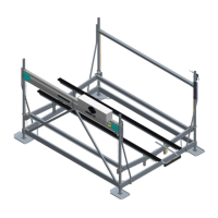
Connect base pads to leg tubes and assemble the lower side frame, leaving hardware loose for adjustment.
Attach crossmembers and corner brackets, then square and tighten all lower frame hardware for stability.
Lay cradle tubes across the frame, attach corner guides and side rail brackets using specified hardware.
Mount galvanized cradle tubes and corner guides, then attach platform side rails to the bottom frame.
Route level cables through sideframe holes and install spacer brace tubes on posts opposite cable brackets.
Insert level cable ends into the spacer brace tube and secure with specified hardware per the chart.
Position the hydraulic lift tube assembly, securing it with brackets and hardware according to model specifications.
Consult the measurement table to correctly position lift tube and brace tube components for proper operation.
Mount the pump box and connect battery cables to the pump, wiring the battery bank for 12V or 24V systems.
Mount battery tender charger or solar charger unit as per instructions for optimal battery maintenance.
Mount the dockside control box and cord unit to the dock post and connect it to the pump for system operation.
Secure lift tube cables to cradle tubes or steel brackets using nuts and washers, referring to the hardware chart.
Mount the upper limit switch to the winch tube assembly, allowing adjustment for proper cable travel.
Install braces for larger lift models and insert black plastic caps into leg posts as a final assembly step.
| Brand | ShoreStation |
|---|---|
| Model | SSV50120HS |
| Category | Lifting Systems |
| Language | English |