This document provides assembly instructions for Shore Station hydraulic boat lifts, covering various models from 4000# to 15000# capacity. The primary function of these devices is to lift and store boats out of the water, utilizing a hydraulic system for operation.
Technical Specifications:
The manual details several models with varying dimensions for lower frame components (front & rear crossmembers and side frames) and specific bolt sizes for assembly. For instance:
- SSV40108HS & HSDW: 5" X 2" X 107" crossmembers, 5" X 2" X 131" side frames, using 3/8-16 X 6" short bolts and 3/8-16 X 6 1/2" long bolts.
- SSV60120HS & HSDW: 6" X 2" X 119" crossmembers, 6" X 2" X 143" side frames, using 3/8-16 X 7" short bolts and 3/8-16 X 7 1/2" long bolts.
- SSV150144HSDW: 8" X 2" X 143" crossmembers, 8" X 2" X 185" side frames, using 3/8-16 X 8 1/2" short bolts and 3/8-16 X 9" long bolts.
The lift tube and brace tube heights (X and Y measurements, respectively) are critical for proper assembly and vary by model. For example:
- SSV40108HS: Lift Tube Height (X) 71-1/2", Brace Tube Height (Y) 75-1/2".
- SSV60120HS: Lift Tube Height (X) 80", Brace Tube Height (Y) 75-1/2".
- SSV150144HSDW: Lift Tube Height (X) 109", Brace Tube Height (Y) 102".
These measurements can vary up to 1 1/2" due to cable length variation, requiring adjustment to ensure the platform is level and cables reach the cradle attachment.
Hardware specifications include:
- Base Pad Assembly: HEX LOCKNUT 3/8 BRASS/NYLON INSERT, CARR 3/8-16 X 1 GR5.
- Base Pads to Legs: 1/2-13 X 4 1/2” HC Stainless bolts and brass lock nuts with nylon inserts.
- Lower Side Frame: HEX LOCKNUT 3/8 BRASS/NYLON INSERT, WASHER USS FLAT 3/8 STAINLESS.
- Lift Platform (4000#-6000#): CARR 3/8-16 X1 1/4 SS, HEX LOCKNUT 3/8 BRASS/NYLON INSERT, WASHER USS FLAT 3/8 STAINLESS, CARR 3/8-16 X1 GR5, HH 5/16-18 X 3/4 CS STAINLESS, WASHER USS FLAT 5/16 STAINLESS, HEX LOCKNUT 5/16-18 BRASS /NYLON.
- Lift Platform (8000#-15000#): HH 3/8-16 X 1 1/2 CS STAINLESS, WASHER USS FLAT 3/8 STAINLESS, HEX LOCKNUT 3/8 BRASS/NYLON INSERT.
- Side Spacer Brace Tube (4000#-6000#): WASHER USS FLAT 3/8 STAINLESS, HEX LOCKNUT 3/8 BRASS/NYLON INSERT, HH 3/8-16 X 3 3/4 CS STAINLESS.
- Side Spacer Brace Tube (8000#-15000#): WASHER USS FLAT 1/2 STAINLESS, HEX LOCKNUT 1/2-13 BRASS/NYLON, HEX LOCKNUT 3/8 BRASS/NYLON INSERT, WASHER USS FLAT 3/8 STAINLESS, HH 3/8-16 X 2 CS STAINLESS, HH 1/2-13 X 5 1/2 CS STAINLESS.
- Hydraulic Lift Tube/Assemblies (4000#-6000#): HH 1/2-13 X5 1/2 CS STAINLESS, WASHER USS FLAT 1/2 STAINLESS, HEX LOCKNUT 1/2-13 BRASS/NYLON.
- Hydraulic Lift Tube/Assemblies (8000#): HH 3/8-16X2 CS STAINLESS, HH 1/2-13 X5 1/2 CS STAINLESS, WASHER USS FLAT 3/8 STAINLESS, HEX LOCKNUT 3/8 BRASS/NYLON INSERT, WASHER USS FLAT 1/2 STAINLESS, HEX LOCKNUT 1/2-13 BRASS/NYLON.
- Hydraulic Lift Tube/Assemblies (10,000# & 15,000#): WASHER USS FLAT 3/8 STAINLESS, HH 3/8-16 X 2 CS STAINLESS, HEX LOCKNUT 3/8 BRASS/NYLON INSERT.
- Braces for 8000# Lifts and Larger: HEX NUT 3/8-16 BRASS, LOCKWASHER 3/8 S/T MED STAINLESS, WASHER USS FLAT 3/8 STAINLESS, RUB 3/8-16 X 2 3/8 X 2 5/8 SS, HEX LOCKNUT 3/8 BRASS/NYLON INSERT, RUB 3/8-16X27/16X5 SS.
Usage Features:
The assembly process is broken down into several steps, emphasizing careful sorting of hardware and sequential construction.
- Base Pad Assembly: Channel clamps are aligned with base pads, and bolts are inserted from the bottom up and secured with lock nuts.
- Base Pads to Legs: Adjustable leg tubes are attached to base pads using bolts and brass lock nuts.
- Lower Side Frame Assembly: Legs are laid down, corner blocks are used, and sideframe tubes are secured with short bolts, flat washers, and brass lock nuts. It is crucial not to tighten these fasteners at this stage.
- Frame Corner Assembly: The entire assembly is flipped upright. Long bolts and bottom corner cable brackets are used to secure the frame, again with a directive not to tighten until later.
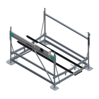
- Bottom Frame & Post Assembly Completion: Remaining leg assemblies are inserted, and short bolts with washers are used to keep them in place. The frame is then squared, and all installed hardware is tightened.
- Lift Platform Assembly (4000#, 5000#, 6000#): V-shaped cradle tubes are laid across the lower frame. Carriage bolts are inserted into corner guides and slid into the top slot of the cradle tube, secured with flat washers and lock nuts. Side rail brackets are mounted on each end of the cradle tube, ensuring equal distance from the ends for squareness. Platform rails are inserted and secured with bolts, washers, and nuts. It is important not to tighten at this time.
- Lift Platform Assembly (8000#-15000#): Galvanized steel cradle tubes are used, with plastic and aluminum ring-style corner guides. Corner guides slide over the post and attach. Platform side rails are placed between welded brackets on the cradle tube and attached using the same fasteners as the lighter models.
- Level Cable Attachment: Level cables are inserted through holes in the cradle tube and secured with flat washers and two brass hex nuts. The first nut is run to the bottom of the threads, and the second is tightened against it.
- Side Spacer Brace Tube Installation: The side spacer brace tube is installed on the posts opposite the corner cable brackets. Appropriate brackets and hardware are used, and the spacer tube is mounted to the post, keeping lock nuts on the outside. Brackets are adjusted to the height indicated in the chart, and all fasteners are securely tightened.
- Level Cables to Spacer Brace Tube Attachment: Level cables from the cradle tubes are inserted through the spacer brace tube and secured with hardware. The platform should be blocked off the lower frame by about 6 inches to create slack.
- Hydraulic Lift Tube/Assemblies Installation: The heavy hydraulic lift tube (containing the cylinder) is positioned on the side of the lift with corner cable brackets, cables exiting the bottom, and hydraulic ports facing outward. Brackets are attached at the height indicated in the chart, and all fasteners are securely tightened. For 10,000# and 15,000# models, 1/2" lock nuts on the plates need to be loosened (but not removed) to allow the assembly to slide down over the corner post to the correct position.
- Pump Box Mounting: Battery is placed in the pump box, and red/black battery cables are attached to positive/negative posts, respectively. A short Battery Tender harness is also attached, matching colored cable ends. Cables must not contact each other or any part of the lift.
- Battery Connection (12-Volt Pump): Positive and negative cables from the battery are mounted as shown.
- Battery Connection (24-Volt Pump): The long black ground cable connects to the negative post. A short black cable connects batteries (positive on one to negative on the other). The red battery cable connects to the positive on the battery. The battery cable from the battery bank connects to the motor battery cable.
- Dockside Control Box w/Lockout: The control box and 35-foot cord unit are mounted to the post on the dock side of the lift. The cord is routed through the canopy and attached to the hoop with zip ties or an underwater conduit kit. Hose clamps are used to secure the controller bracket to the leg post. The connector is plugged into the pump. Remotes are programmed/checked.
- Lift Tube Cables Connection: The Key Fob remote controller is used to run cables down. For aluminum cradle tubes, cables from the outside pulley go through outside holes, and cables from the inside pulley go through inside holes. For steel cradle tubes, both cables attach to welded cable mounting brackets. Cables are secured with two brass nuts and a flat washer.
- Upper Limit Switch Attachment: The upper limit switch is attached to the bottom of the winch tube assembly. The holes allow adjustment for the cable to travel through the center of the pivot arm slot. Bump stop halves are mounted to the cable with carriage bolts and kep nuts, with final placement done after the lift is in water and the boat is loaded.
- Battery Tender Mounting: The Battery Tender charger (HA0083 for 12V, HA0084 for 24V) is plugged into a 110-volt power line. It includes the charger unit, power cord, short battery harness, and a 25 ft. connecting cord.
- Boat Lift Solar Charger (HA0110 for 12V, HA0135 for 24V): These chargers are designed for reliable charging and maintenance of the lift battery. Proper installation maximizes performance.
- Mounting Braces for 8000# Lifts and Larger: Braces are mounted to the hoists using specified hardware.
- Step Kit Assembly and Attachment (4000#-6000# with Drop Sides): Instructions for this HA kit are included separately.
- Inserting Caps: Black plastic caps are inserted into the top of the leg posts. This step is omitted if a canopy is added.
Maintenance Features:
- Tightening Fasteners: After assembly, all fasteners must be tightened with an air or battery-powered high torque impact wrench. It's crucial for the platform tube to pull tight to the corner block, slightly creasing the tube wall until there is no gap. Hand tightening may be necessary if the impact wrench lacks sufficient torque.
- Cable Management: Ensure all cables are secured, and all hoses and electrical connections are together.
- Battery Tender: The Battery Tender is designed to rapidly recharge the battery and then maintain a full charge, contributing to battery longevity.
- Solar Charger: The solar charger provides reliable, trouble-free charging and maintenance for the lift battery.
- Final Check: Before considering assembly complete, a final walk-around is recommended to ensure all nuts and bolts are tightened, all cables are secured, and all hoses and electrical connections are properly arranged.
- Upper Limit Switch Adjustment: The final placement of the bump stop for the upper limit switch is made once the lift is in the water and the boat can be loaded, allowing for precise adjustment.
- Cable Contact Prevention: When mounting the pump box, ensure battery cables do not make contact with each other or any part of the lift.