Do you have a question about the ShoreStation Manual SSV30108MS and is the answer not in the manual?
Sort hardware and other contents by size to identify fasteners for lift assembly.
Assemble four base pads by attaching channel clamps to base pads using bolts and lock nuts.
Attach base pads to legs using leg lift rods, channel clamps, and hair pin cotters.
Connect sideframe tubes to corner blocks using specified bolts and washers, do not tighten.
Attach front and rear frame crossmembers to corner blocks with bolts and washers, do not tighten.
Insert long bolts and corner cable brackets into frame tubes and secure with washers and lock nuts.
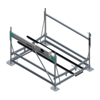
Insert remaining leg assemblies into crossmembers, secure with bolts, and square the frame.
Attach V-shaped cradle tubes and side rail brackets to the lower frame using carriage bolts.
Insert level cable into sideframe hole and secure with washer and brass hex nuts.
Install drop side or spacer brace tube on posts opposite corner brackets, adjust height, and tighten.
Mount the lift tube to the post assembly, adjust bracket height, and tighten fasteners securely.
Insert level cables through drop side or brace tube and secure with nuts and washers.
Lower winch assembly into winch tube, align holes, and secure with hex bolt, washer, and locknut.
Route lift cable through cable pocket, insert cable wedge, and loop cable end into pocket.
Install wheel stop bracket and associated hardware on manual lifts as per diagram.
Secure lift tube cables to cradle tubes using brass nuts and flat washers per chart specifications.
Attach upper limit switch to winch tube assembly, allowing adjustment for cable travel.
Mount the battery box and battery tender according to kit instructions.
Install bunks, pontoon kit, and log rack/loadguide as per kit and hardware box instructions.
Attach the optional motor stop kit for 2000# lift models as per HA kit instructions.
Insert black plastic caps into the top of the leg posts as a final step.
This document serves as an assembly guide for Shore Station boat lifts, specifically covering manual and FlexPower® electric models ranging from 2000 LB to 6000 LB. The guide provides detailed, step-by-step instructions for assembling the various components of the boat lift, ensuring proper setup and functionality.
The Shore Station boat lift is designed to safely store and launch boats, protecting them from water damage, marine growth, and environmental factors when not in use. It achieves this by lifting the boat out of the water, providing a dry storage solution. The system consists of a robust frame, a lifting platform (cradle), and a winch mechanism (either manual or electric) that raises and lowers the platform. The lift is supported by adjustable legs with base pads, allowing for stable placement in varying water depths and bottom conditions.
The core function involves the controlled movement of the boat platform. When lowering, the platform descends into the water, allowing the boat to float off. When raising, the platform lifts the boat clear of the water, securing it above the waterline. This mechanism is crucial for preserving the boat's hull, reducing maintenance, and extending its lifespan. The inclusion of both manual and electric winch options caters to different user preferences and operational needs, offering flexibility in how the boat is handled.
The assembly process begins with sorting hardware, emphasizing the importance of identifying fasteners using a provided finder sheet. This ensures that the correct components are used at each stage, preventing assembly errors. The initial steps focus on assembling the base pads to the adjustable legs, which are critical for the lift's stability and adaptability to different lakebed conditions. The leg lift rods, secured with hair pin cotters and grips, allow for easy adjustment of the leg height, a key feature for accommodating fluctuating water levels.
The construction of the lower side frame involves laying down legs with corner blocks and attaching sideframe tubes and crossmembers. The guide highlights the importance of matching legs according to decals and using specific bolts and washers. A crucial instruction is to "DO NOT TIGHTEN" fasteners at this stage, indicating that final tightening occurs after the frame is squared, which is a common practice in structural assembly to ensure proper alignment.
The complete frame corner assembly involves flipping the unit upright onto the base pads and securing the frame tubes with long bolts and bottom corner cable brackets. The guide provides a detailed chart for selecting the correct lower frame components and bolts based on the specific lift model (e.g., SSV20100, SSV30108, SSV50120), including dimensions for front & rear crossmembers, sideframes, and bolt lengths. This ensures that users select the appropriate parts for their particular lift, which is essential for structural integrity and safe operation.
A significant usage feature is the emphasis on properly securing the lift's lower frame. The guide explicitly states: "Tighten all fasteners with an air or battery powered high torque impact wrench. It's important to tighten the fasteners so the platform tube pulls tight to the corner block. The fastener needs to slightly crease the tube wall until there is no gap between the tube and the corner block. In some instances the impact wrench may not have enough torque and it may be necessary to hand tighten in order to achieve contact with the corner block." This detailed instruction underscores the critical nature of secure connections for the lift's stability and safety, preventing structural weaknesses that could arise from loose components.
The assembly of the lift platform involves laying V-shaped cradle tubes across the lower frame. The guide specifies that the end with the lift cable threaded out the bottom should be on the same side as the corner cable brackets. Side rail brackets are mounted on each end of the cradle tube using carriage bolts, with a specific instruction to position the outer edge of the brackets at least 3 inches from the end of the cradle tube and to keep this distance equal on all four corners to ensure the platform remains square. Corner guides are also secured with carriage bolts, flat washers, and lock nuts, again with the instruction not to tighten immediately.
Platform rails are inserted between the mounting brackets and V-frames. For 2000# models, spacers are required under the I-beam and on top of the lower mounting bracket, highlighting model-specific variations. The guide includes a detailed illustration showing the position of the level cable as it comes over the pulley in the cradle tube and out the bottom to go to the cable mounting bar attached to the corner of the lower frame. This visual aid is crucial for correct cable routing, which is fundamental to the lift's leveling mechanism.
Attaching the level cable involves inserting it into the hole closest to the sideframe and securing it with a flat washer and two brass hex nuts. The instruction to run the first nut to the bottom of the threads and the second tightly against the first ensures a secure and stable connection.
The installation of the drop side or spacer brace tube is another key feature. These tubes are located opposite the lift tube and are installed on the posts. The guide differentiates between EDS (Electric Drop Side) and M (Manual) lifts, specifying that 2000# thru 6000# EDS lifts use a drop side brace tube, while 2000# thru 5000# M lifts use a spacer brace tube. Appropriate brackets and hardware are used, with lock nuts on the outside, and adjusted to a height indicated by a chart on page 12.
Mounting the lift (winch) tube assembly follows a similar process, with the lift tube mounted to the post, lock nuts on the outside, and brackets adjusted to the specified height. The guide provides separate illustrations and hardware lists for 2000# thru 4000# lifts and 5000# thru 6000# lift tube assemblies, acknowledging the differences in design and components for various weight capacities.
A critical step for manual and electric winches is their mounting. The winch assembly is lowered into the winch tube, holes are aligned, and it's secured with a stainless steel hex bolt, flat washer, and brass hex locknut with a nylon insert. For FlexPower® Winch Assemblies, the guide specifically warns to ensure the cable goes behind the anti-backwind switch lever, a safety feature to prevent cable tangles or damage.
Attaching the lift/winch cable to the winch drum assembly involves locating the cable wedge pocket and rotating the winch drum until the pocket is in the shown location. The cable end is looped back into the pocket, the cable wedge is inserted, and the cable loop is pulled into the pocket. The guide also specifies that the lift cable should come up through the cable pocket on the side closest to the winch drum, ensuring proper cable routing and operation.
For manual lifts, attaching the wheel stop is detailed, showing how the wheel stop bracket is mounted to the aluminum cradle. This prevents the wheel from over-rotating and ensures safe operation.
Connecting the lift tube cables involves routing the cables from the mechanical winch lifts down to the lift platform. The guide explains that the cable from the outside pulley of the lift tube goes through the outside holes in the cradle tube, and the cable from the inside pulley goes through the inside hole. These cables are secured with two brass nuts and a flat washer, with reference to a chart for proper sizes.
For FlexPower® lifts, attaching the upper limit switch is crucial. This switch is mounted to the bottom of the winch tube assembly, and its holes allow for adjustment so the cable travels through the center of the slot in the pivot arm. A grommet and wire tie are mounted to the cable, with the final placement made only after the lift is in the water and the boat loaded, indicating a fine-tuning step for optimal performance and safety.
The guide also outlines the mounting of the battery box and battery tender, referring to separate HA kits for detailed instructions, which suggests these are optional or supplementary components for electric models. Similarly, mounting the support structure, including bunks, pontoon kits, and pontoon log racks/loadguides, refers to instructions included with the HA Kit or Hardware Box, indicating modularity and customization options for different boat types.
The final steps involve attaching the motor stop (with different kits for 2000# and 3000# thru 6000# lifts) and inserting black plastic caps into the top of the leg posts. The guide notes that if a canopy is being added, the cap insertion step can be omitted. The concluding instruction emphasizes a final check: "Before calling your assembly complete take one last walk around your hoist and make sure all nuts and bolts have been tightened, all cables are secured, and all hoses and electrical connections are together." This comprehensive final inspection ensures that the lift is fully assembled, secure, and ready for safe operation.
While the document is primarily an assembly guide, several instructions implicitly contribute to the long-term maintenance and reliability of the device. The emphasis on proper tightening of all fasteners with a high-torque impact wrench, ensuring no gaps between tubes and corner blocks, directly prevents loosening over time due to vibrations or operational stresses. This meticulous assembly reduces the likelihood of premature wear and structural fatigue.
The detailed instructions for cable routing, including ensuring the FlexPower® cable goes behind the anti-backwind switch lever and proper attachment to the winch drum and cradle tubes, are crucial for preventing cable fraying, tangles, or damage. Correct cable management extends the life of the cables and ensures smooth, reliable lifting and lowering operations.
The adjustable nature of the leg lift rods and the ability to fine-tune the upper limit switch after the lift is in the water allow for optimal setup that minimizes strain on the system. A properly adjusted lift operates more efficiently, reducing wear and tear on the winch, cables, and frame components.
The final inspection checklist, which requires verifying all nuts and bolts are tightened, cables are secured, and all hoses and electrical connections are together, serves as a critical maintenance check at the point of assembly. This practice helps identify and rectify any potential issues before the lift is put into service, contributing to its overall longevity and safe operation. Although not explicitly a "maintenance schedule," the thoroughness of the assembly process lays a strong foundation for minimal maintenance needs during the lift's operational life.
| Lift Operation | Manual |
|---|---|
| Lifting Capacity | 3000 lb |
| Canopy Width | 108 in |
| Weight Capacity per Bunk | 1500 lbs |
| Bunk Carpeting | Yes |